A few months ago I documented the process for creating a large 7-segment LED display. After figuring out the pin locations, the wiring, and the code, I attached an Arduino Nano to a daughter board to create a beautiful self-contained 4-digit display.
Adding a Real-Time Clock (RTC)
When co-blogger, Allan, saw my setup he insisted on attaching a Real-Time Clock (RTC) and buttons so that the unit could be used for timekeeping and as a programmable counter.
We set about making a new daughter board to replace the one I'd made to connect the Arduino to the chips I was using to control the LEDs.
The new board would incorporate the original Arduino Nano and an RTC3231. We decided to use an existing RTC board that we had lying around, instead of recreating its circuitry on our own. All we’d do is plug the board into our new PCB.
Messing with Pins
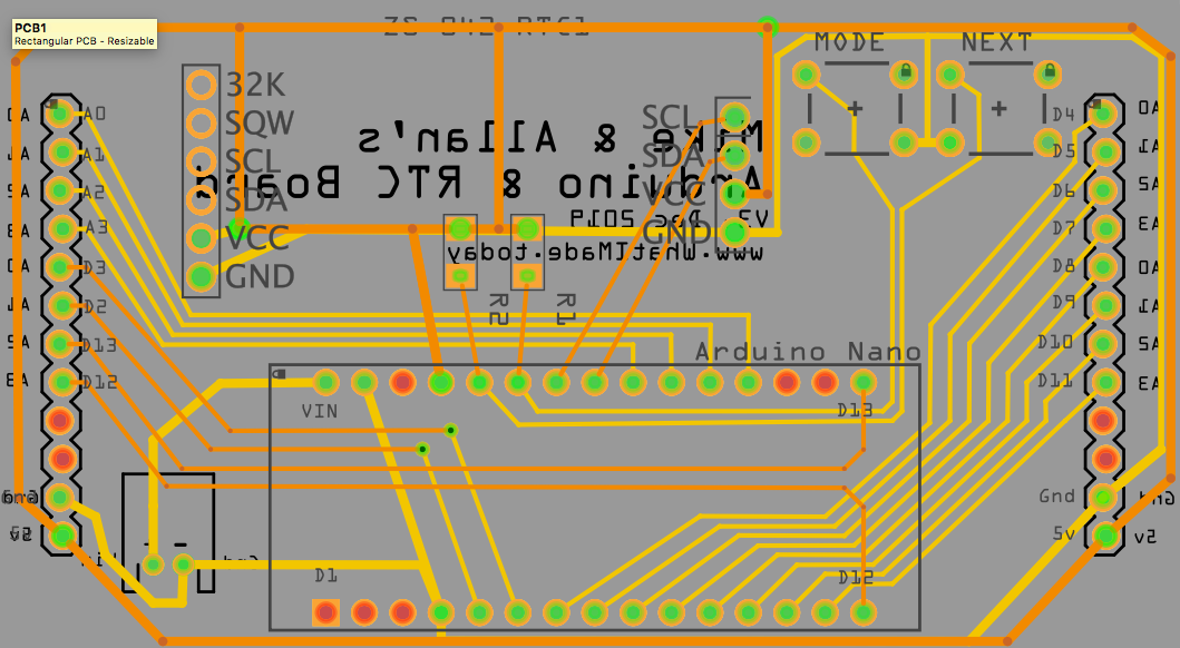
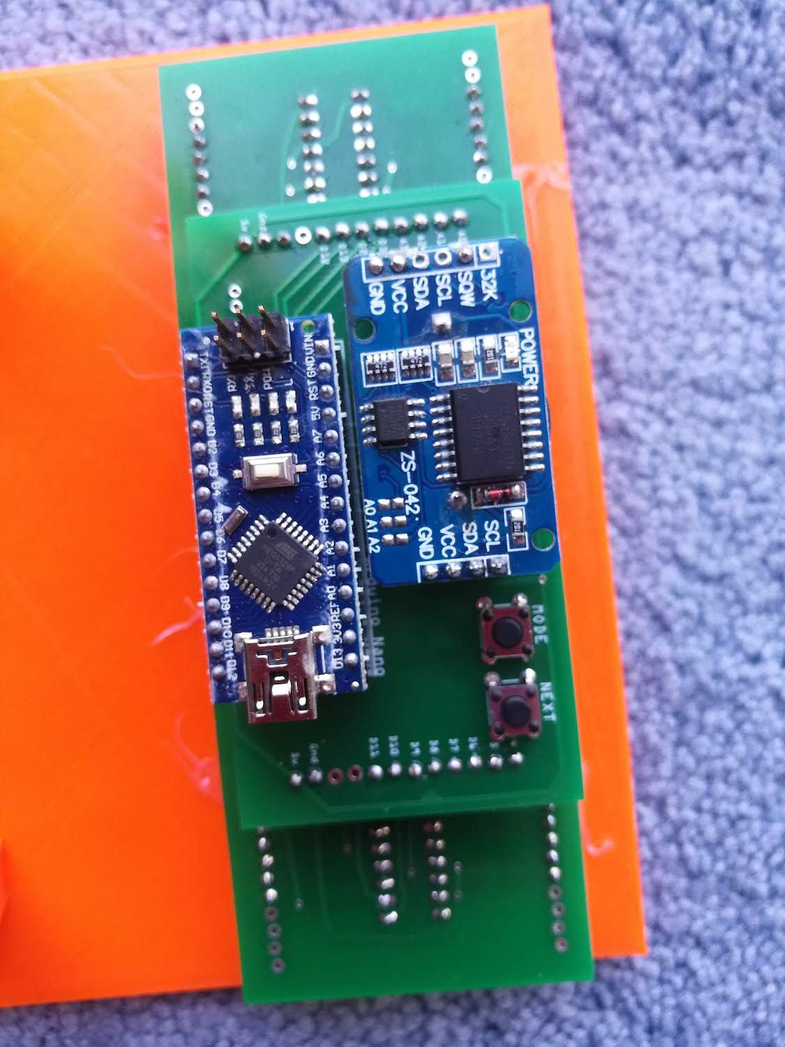
This is the board that Allan created.
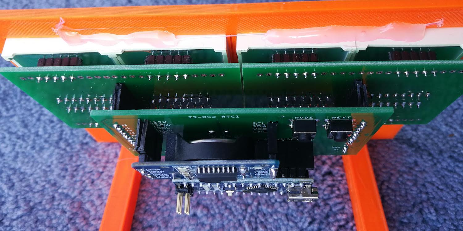
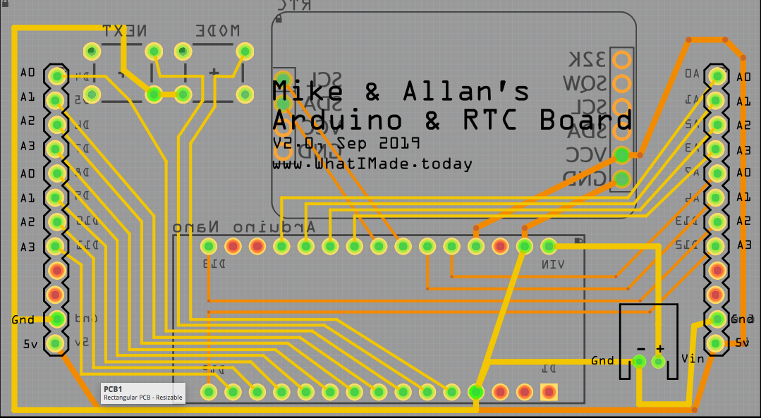 With both top and bottom layers, it's a bit hard to view, but essentially, the new board incorporates the original Nano, an RTC3231, and a couple of buttons.
To make the PCB traces neat, Allan exchanged a couple of my original digital pins with analog pins A6 and A7 instead. (Note these numbers because they become critical later).
PCBs
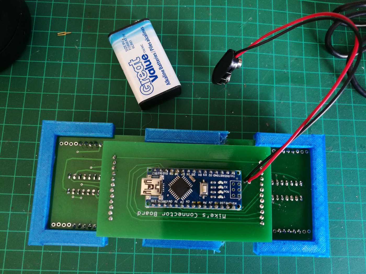
When the PCBs arrived, I got to work soldering the parts in place. Because of the new pin allocations, we’d need to re-program the Arduino sketch - but that’s for later.
After soldering everything, I carefully checked the new pin numbering and made my adjustments to the sketch. Once I was happy everything was in order, I powered up.
As Usual, Something’s Wrong
For some reason, my display wasn’t working properly; digits jumped around seemingly at random. I assumed a wrong connection or a poor solder joint, so I went around everything again, checking and re-checking.
An hour later I was no further on. Everything seemed properly connected, but no matter what I did, I couldn’t stop the jumping numbers.
“I think you need pullup resistors,” advised Allan by VoIP from the other side of the world. “Use your oscilloscope to see what’s coming out of the pins.”
Like the engineer that he is, he went on to describe at great length how the oscilloscope could be used to identify the problem. I’ve written about this little oscilloscope before. It’s made just for this type of amateur troubleshooting. But as I listened patiently to Allan's instructions, I found my mind wandered looking for an easier way.
Going Back to Binary
I had a brainstorm; while I was constructing this project I’d side-tracked into making a simple binary counter.
By controlling four binary inputs, I could get up to 16 outputs - and that’s how I controlled all four 7-segment LEDs on a single Arduino Nano. Sixteen pins of the Nano fed into four SN74LS47N chips - which then controlled the output to the 7-segment display.
If I could "see" the output from the pins, I could find out which weren't working.
That's when I hit on using four regular LEDs.
This is the pinout to the Nano I am using.
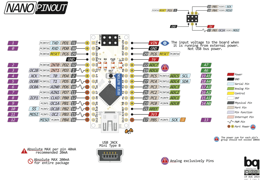
As you can see, the digital pins run from 2-13 (leaving 0 and 1 for RX and TX), and the analog pins are A0 - A7. As most of us know, the analog pins can also be used as digital pins, but not vice-versa.
For our new display we needed:
- For input pins to each of four SN74LS47N chips - 4 x 4 = 16 pins
- Two pins for the RTC - I2C pins A4 and A5
- Two analog pins for the buttons.
There are only 12 digital pins, so on my original board, I used four analog pins (A0 to A3) making up 16 for the SN74LS47N chips.
On Allan’s new board, he needed an extra 4 pins - two for the buttons, and two for the RTC. He took them by using all the digital pins and all the analog pins too. These extra pins were somehow causing a problem.
To pinpoint the issue, all I needed to do was isolate the pins that were giving problematic output. I did this by recreating my simple binary counter with four regular LEDs. If the four pins being tested were functioning properly, I’d get a regular binary count. If they weren’t, my display would not work.
As illustrated in this video, when using pins A6 and A7 I’d get erratic output. All four LEDs are supposed to light as the counter gets to 16 - but only one of them worked. One flickered uncontrollably and the other two did nothing.
So I’d isolated the problematic pins to A6 and A7. At Allan’s suggestion, I put a pull-up resistor on each - but it didn’t help.
By now I’d been troubleshooting for a couple of hours and still hadn’t solved the problem. In frustration, I turned to Google. That’s when I came across this.
So here was the answer. Analog pins A6 and A7 are “only inputs with no digital hardware behind them”. This meant that our custom-made PCB was wrong. Pins A6 and A7 could not be used to feed the SN74LS47N and without re-tracing our board, it would never work.
Hacking the PCB
Studying the PCB I saw I’d need to exchange digital pins D2 and D3 (currently attached to the buttons) with the problematic pins A6 and A7. (My PCB push-buttons are analog input, so there would be no problem using A6 and A7.)
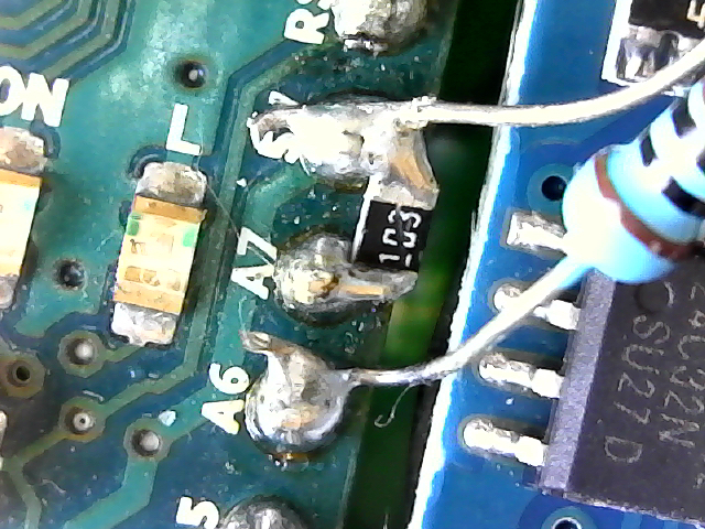
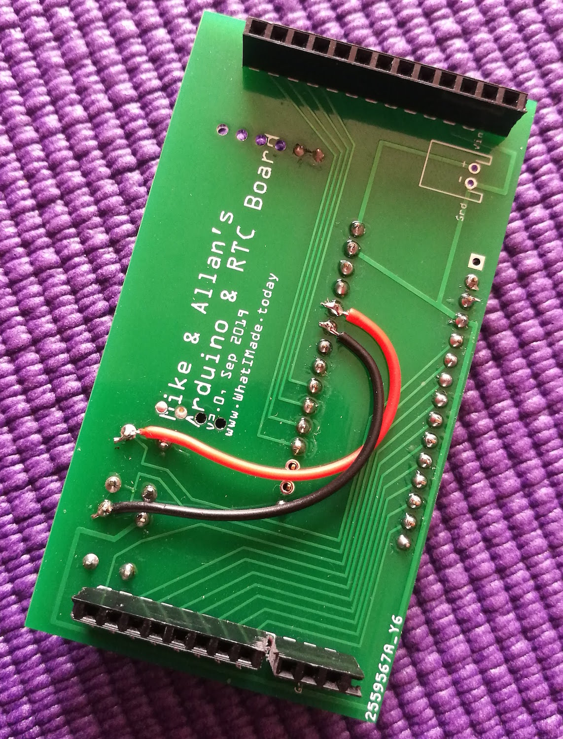
Using a box cutter, I severed the traces to the buttons, then ran wires from pins A6 and A7 to D2 and D3 for the buttons. I then had to connect pins D2 and D3 to the SN74LS47N. Finally, I put a pull-up resistor on each of A6 and A7. My soldering isn't impressive, but with this little bit of hacking, and reprogramming a couple of lines of code, at last, everything started to work.
The photo is a close-up of A6 & A7. I used an SMD resistor to connect A7 to 5v, and a through-hole for A6. It's very, very ugly, but it did the trick!
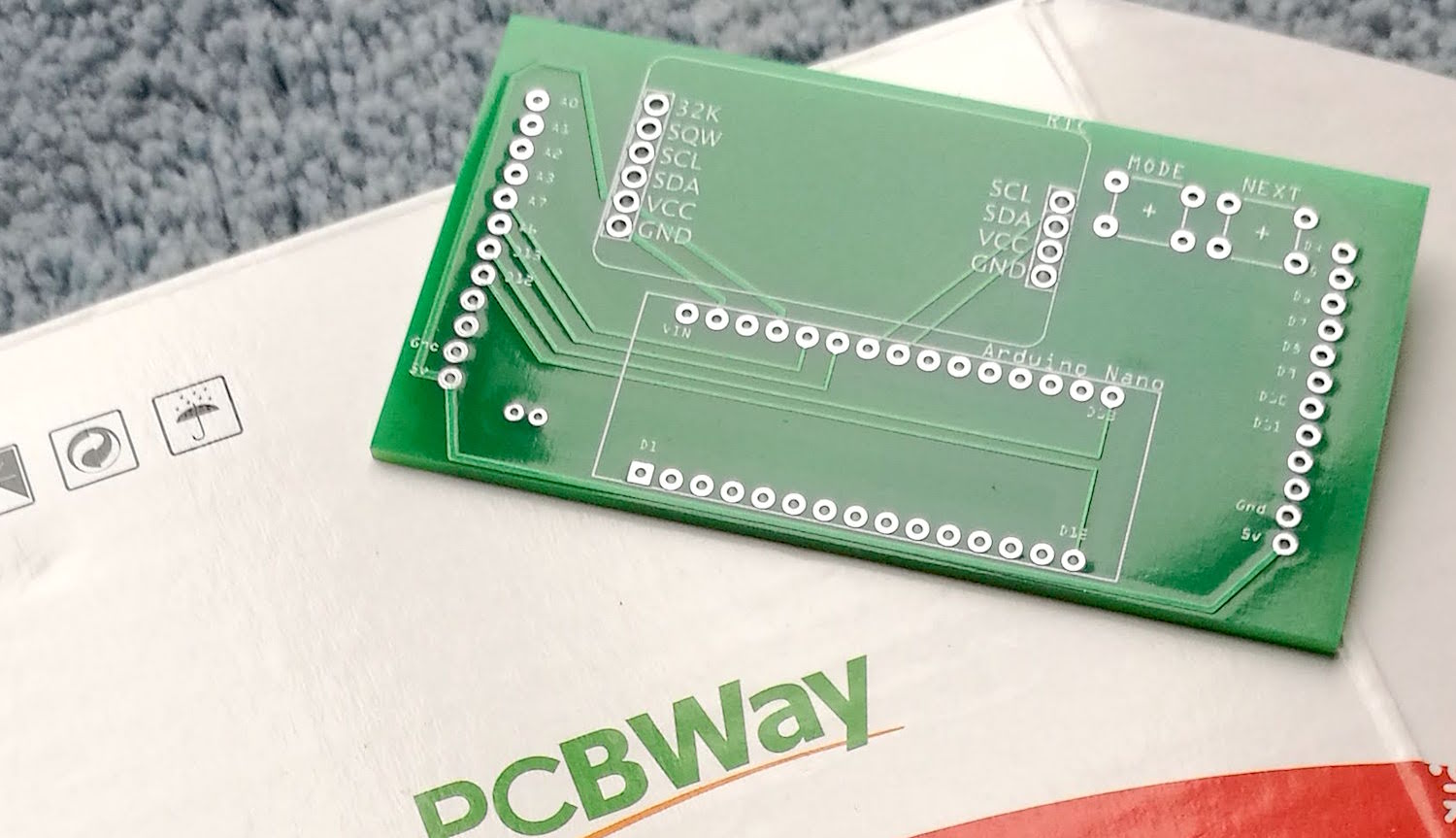
Ordering from PCBWay
Fortunately the good people of PCBWay are readers of this blog and they made us an offer we couldn't refuse. They'd give us a couple of free boards if we gave them credit in our post. This was a perfect opportunity to get a new board, this time with the traces in the proper place.
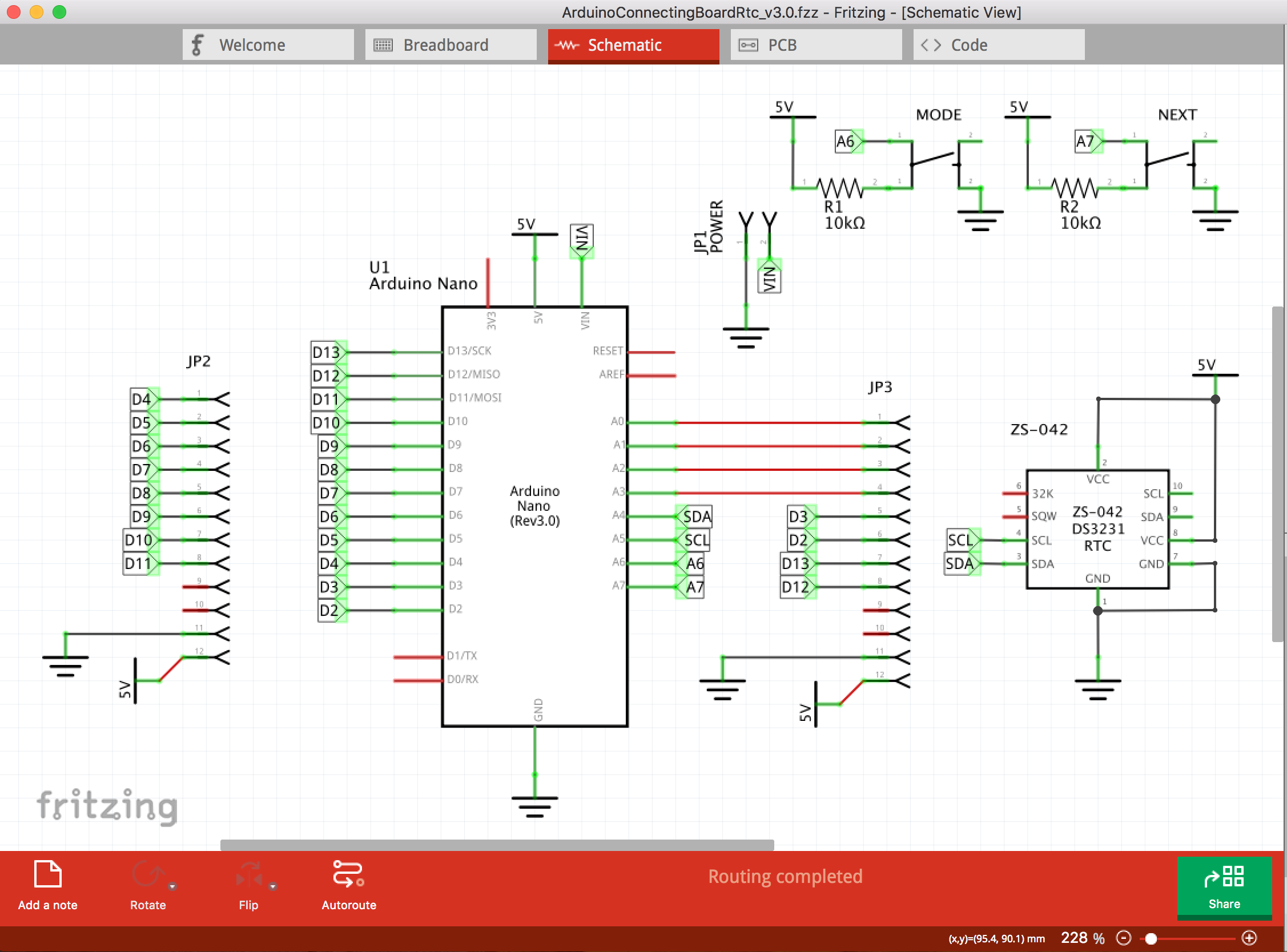
We sat down and re-traced our board on Fritzing. If you study it carefully, you'll see that we've exchanged D2 and D3 with A6 and A7. We also added a couple of surface-mounting pull-up resistors for the buttons.
The boards came out great. All components were properly positioned and soldering went well.
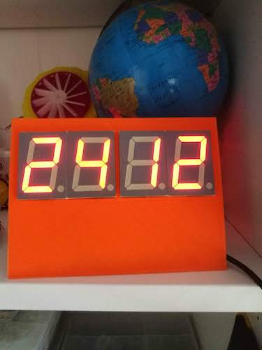
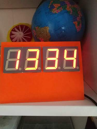
The display now shows three options: time, date, or one-second counter. It can be adjusted by the buttons on the PCB.
The Code
Co-blogger, Allan Schwartz wrote the code that you can view or download here. It's a great example of well-documented, clear but efficient and concise Arduino code.
All project files, including Fritzing files, and schematic are on github here.