This is the hardware part of my odyssey to design and build a large 4-digit, 7-segment display, running on an Arduino Nano. It's a great case-study in figuring out something complicated - by taking small steps, one at a time.
I'm an enthusiastic amateur with no training in electronics. Read on to see how far you can take things with application, patience, and determination.
Software
As I said above, this post deals only with hardware. Once the device is built, you can pretty much make it do anything you want. I'll follow up with another post with some uses for the 7-segment display.
It started with a garage sale
It all started when I picked up four giant 7-segment displays from a garage sale about three years ago. The displays lay in a drawer gathering dust. What stopped me from using them was their size and the amount of wiring I'd need to do; using Dupont connectors and breadboards was clearly not the way to go.
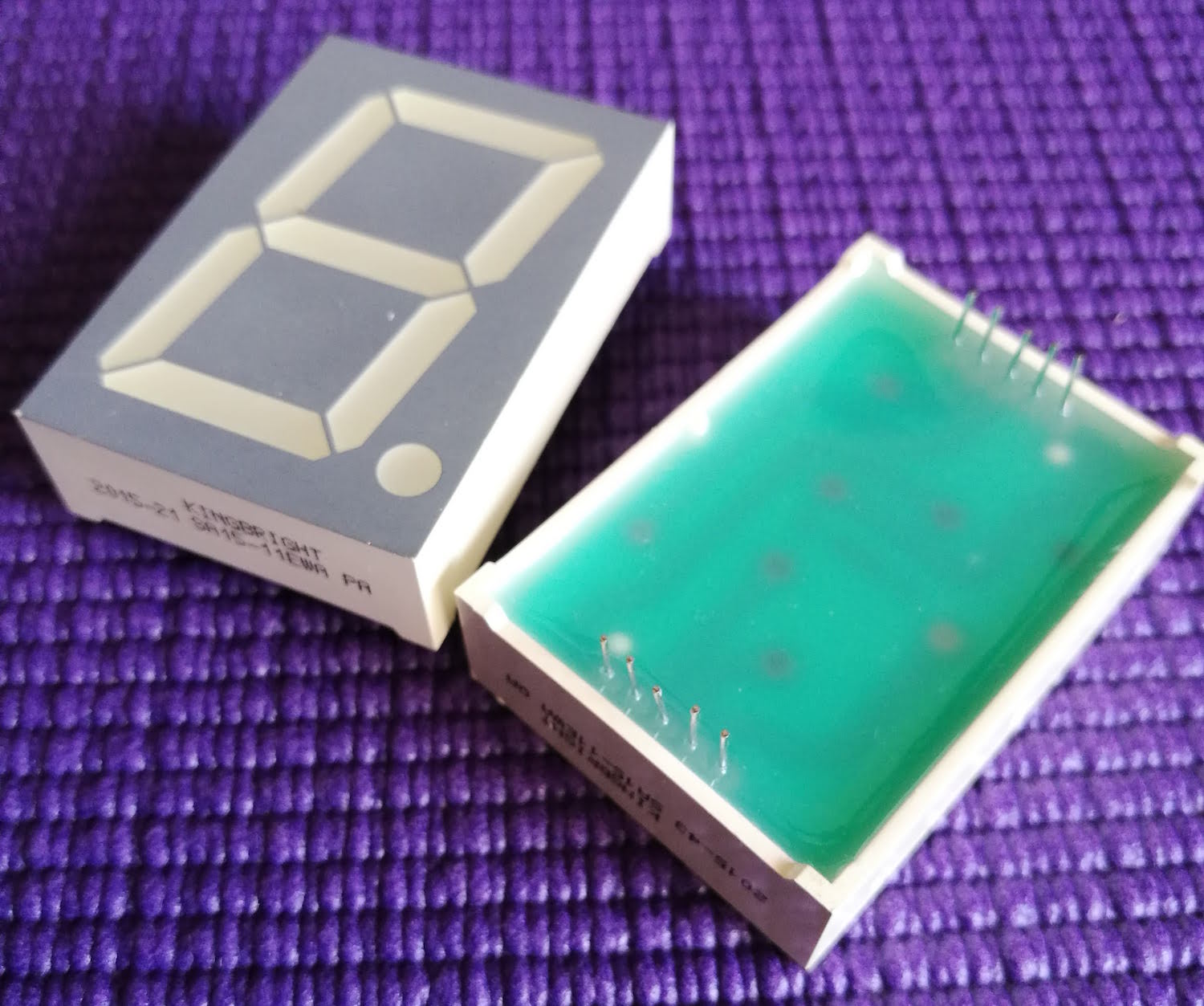
The LED datasheet shows that they're 1.5 inches (3.8cm) in height.
No knowledge
I began with no knowledge at all of a 7-segment LED. All I knew was that it had 7 LEDs and a decimal point. I assumed that each segment could be lit independently - and by lighting them in a certain pattern, I could create a number.
Connecting Pins
So, I connected the pin of each segment to a pin of an Arduino, then worked out which pins needed to light up (go HIGH) to create which digit.
As you can see from the photo above, my LED has 10 pins - 5 at the top and 5 at the bottom.
A quick look at my datasheet reveals this:
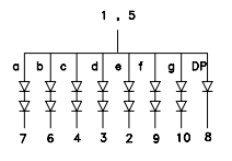
Pins 1 & 5 are Common Anodes, and the rest of the pins are connected to the segments of the LED.
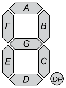
The letters correspond to the standard segment lettering of a 7-segment display:
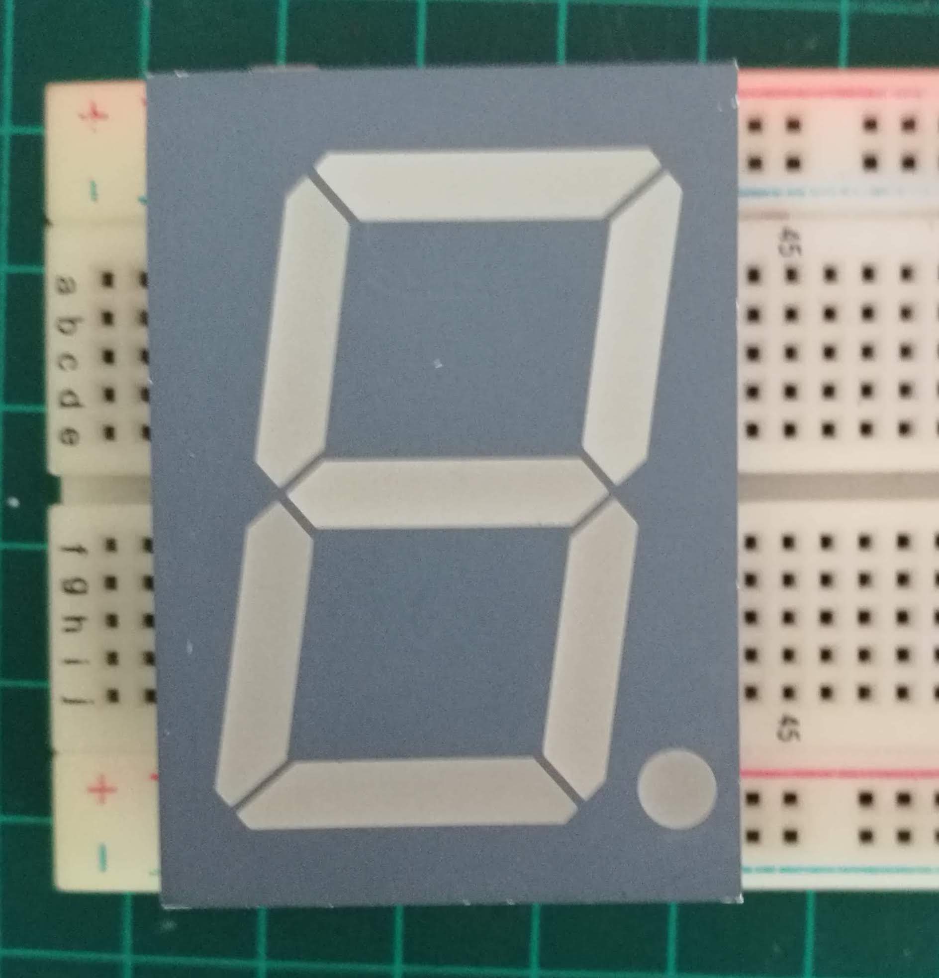
This is where my first problem emerged. Normally I'd put my 7-segment on a breadboard, but because these LEDS were so large, a single breadboard was too small. The only way around it was to put two breadboards side by side.
Current-limiting resistors
Before I move on, I need to mention current-limiting resistors - but so as not to disrupt the flow, I've put the explanation here.
Far too many connections
For each 7-segment LED I have:
- 10 pins of the LED (spread over two breadboards)
- 8 resistors - each with two ends
- The Arduino - using 8 pins + Vin and GND.
This was just about manageable with a single 7-segment LED, but if I wanted to use all four, it would be almost impossible to track all the wires. Added to that, if I used eight Arduino pins for each LED, that's 32 altogether - way too many for a Nano.
Considering alternatives - the MAX7219
We've all heard of the popular MAX7219 that drives the world's LEDs. Co-blogger, Allan has written about them extensively here. Using multiplexing, the MAX7219 can control up to 64 LEDS from just eight pins - perfect for what I wanted to do.
So, I followed Allan's instructions to get my LEDs working with a MAX7219.
I spent more than an hour getting nowhere, until I discovered that the MAX7219 only works with Common Cathode LEDs. Naturally, mine were Common Anode.
Multiplexing, fast switching and optical illusions
This sent me back to the drawing board. Instead of using the MAX7219, I'd create my own multiplexing - essentially, doing what the MAX7219 does - but straight from the Arudino's pins.
So what exactly is multiplexing?
Consider, I have four 7-segment LEDs with 10 pins on each. Each of the 7 segments has its own anode pin.
Let's look again at this diagram:
Imagine the diagram repeated four times - one for each LED. Now, we'll join together all the pins 7, then all the pins 6, 4, and so on until all the cathode pins are connected together. Then connect each of these sets to its own Arduino pin - so, all pins 7 will connect to a single Arduino pin, all pins 6, 4 and so on...
Now let's look at the anode pins of the 4 LEDs (1 and 5 above). Connect each of the four anode pins to a separate Arduino pin. So now we have 8 pins for the cathodes, and 4 pins for the anodes.
Here begins the magic.
Let's turn on a single anode pin and a single cathode pin. You'll see that the corresponding segment of an LED lights up. Now turn off the anode pin, and turn on a different one. You'll now see the same segment of a different LED light up.
If you program the Arduino to do this very rapidly, you'll see the segments blinking on and off so quickly, it gives the illusion they're constantly on. Do this for all the segments and all four LEDs and we create a multiplex of numbers.
Cut down the wiring - making a PCB
With so many pins, resistors and connectors to deal with, I began thinking about creating a Printed Circuit Board. Instead of having wires trailing everywhere, maybe I could design a PCB that would neatly hold it all together?
Before I set about it, I decided to try to design a very simple PCB to see how it went. That's what prompted me to create the Binary Counter PCB I wrote about in my previous post.
I was so pleased with PLCPCB's PCB that I quickly set about designing another - this time to house two 7-segment LEDs. At this early stage, I just wanted a board to mount and connect them. I wasn't thinking of extra electronics.
Fritzing
Using Fritzing, I planned a very simple breadboard.
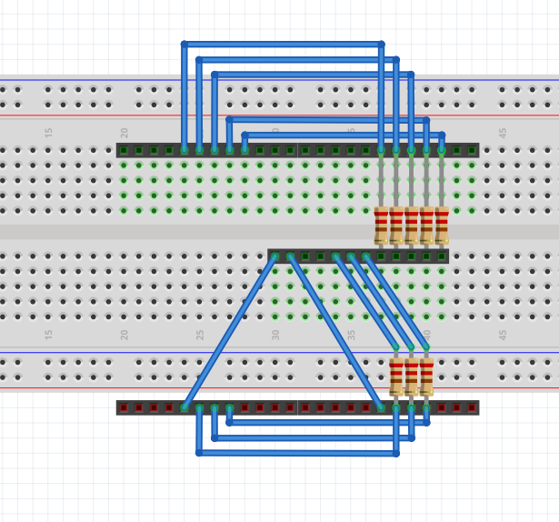
I put five 12-pin headers on the board. For the 7-segment LED pins, I placed two headers together and put them at the top. I did the same for the bottom pins. In the middle, I put another header to which I'd connect the Arduino pins. Current-limiting resistors connected to the 7-segment pins.
Note that I connected together all the cathode pins (ie 7-7, 6-6, 4-4, etc.). At this stage, I still intended to use multiplexing. As no two displays would be on at the same instant in time, a single resistor could serve two displays.
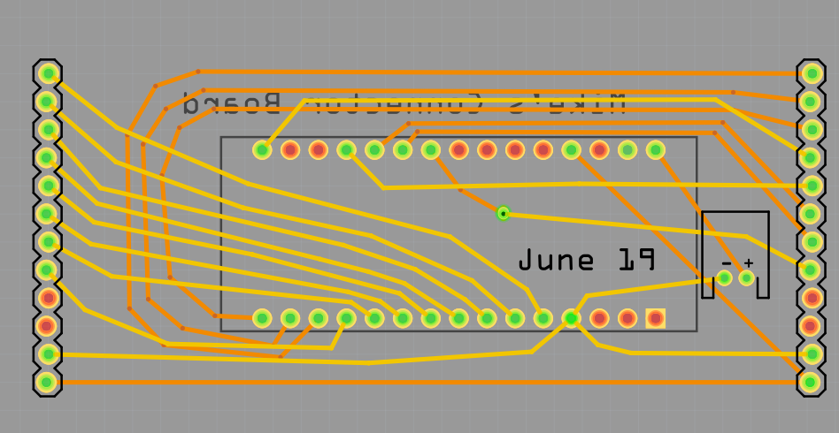
Skipping over to Fritzing PCB design, my board ended up looking like this:
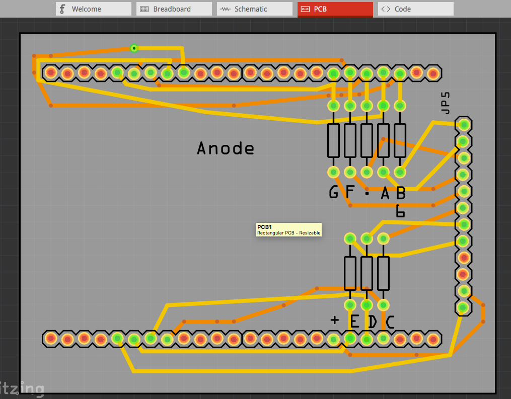
Experienced board builders will laugh at my traces, but working with JLCPCB, is so easy and the boards so simple to make, I just wanted to see if my cobbled attempt would work.
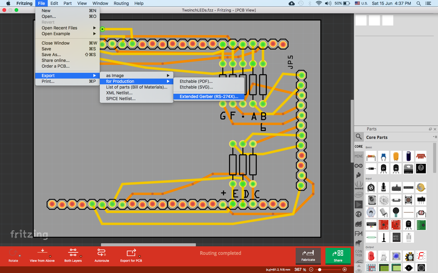
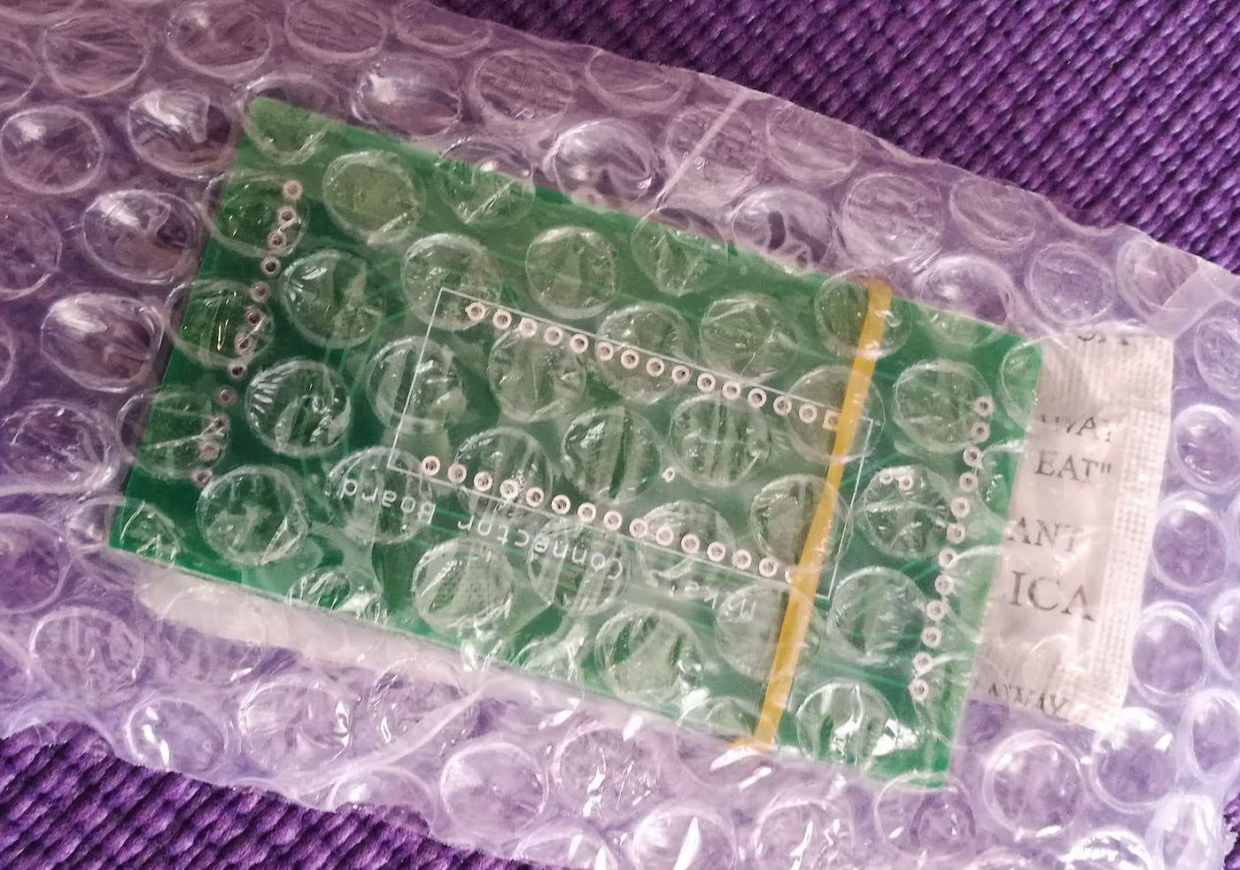
I exported the files for manufacture, uploaded them to JLCPCB, and waited for them to arrive.
With their customary efficiency, for less than $10 (including shipping) the boards arrived within 10 days. I was delighted to find they corresponded exactly to my Fritzing file.
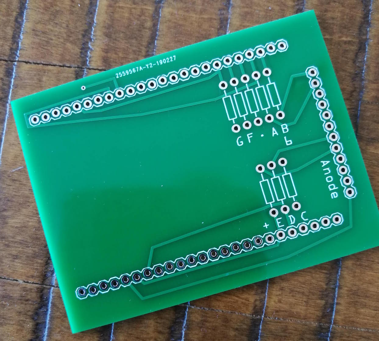
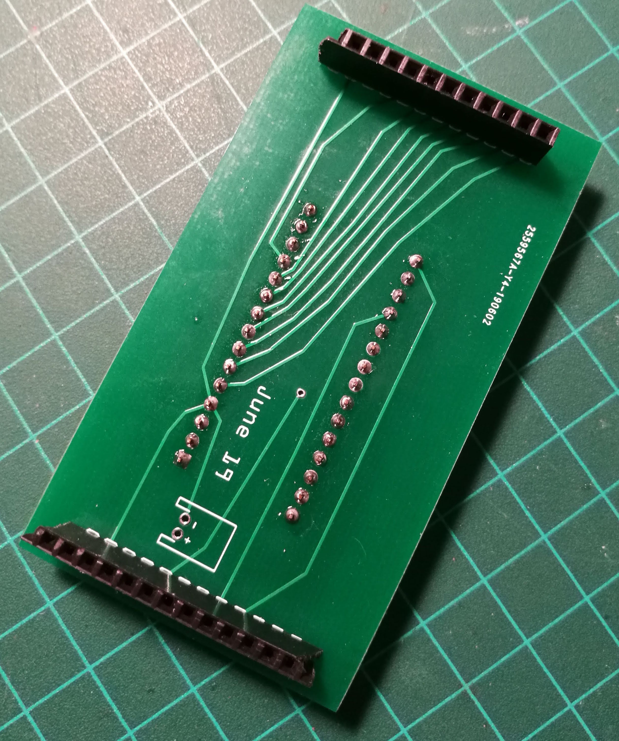
I quickly soldered on my resistors and headers and let out a shriek of delight when I discovered I'd got all my traces right!
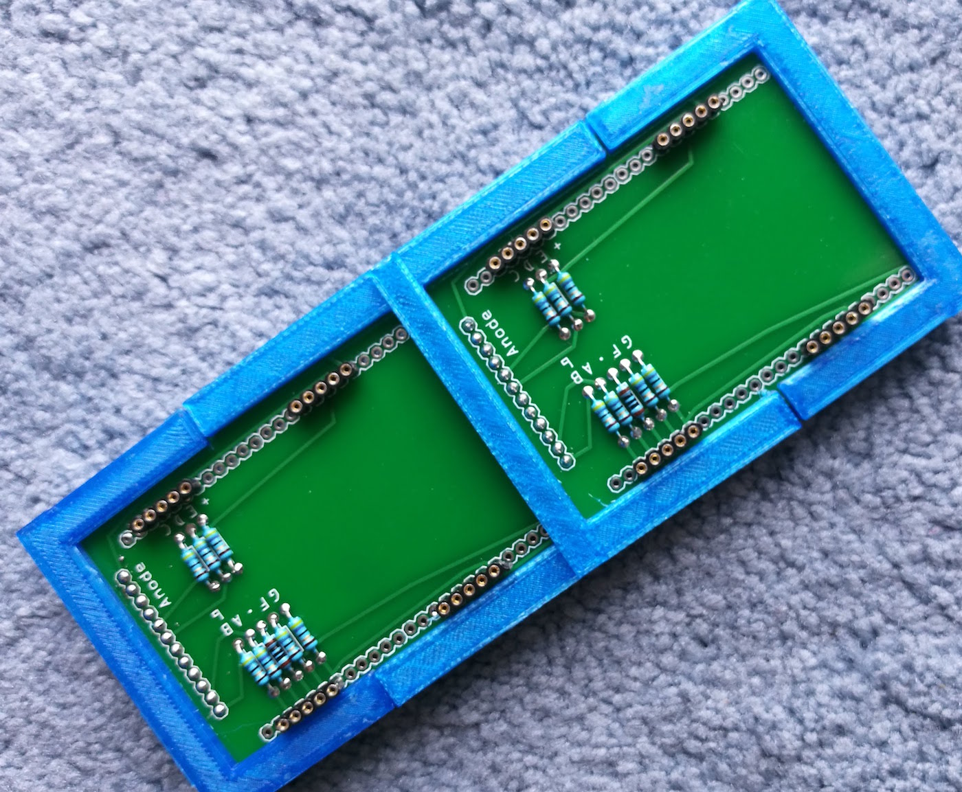
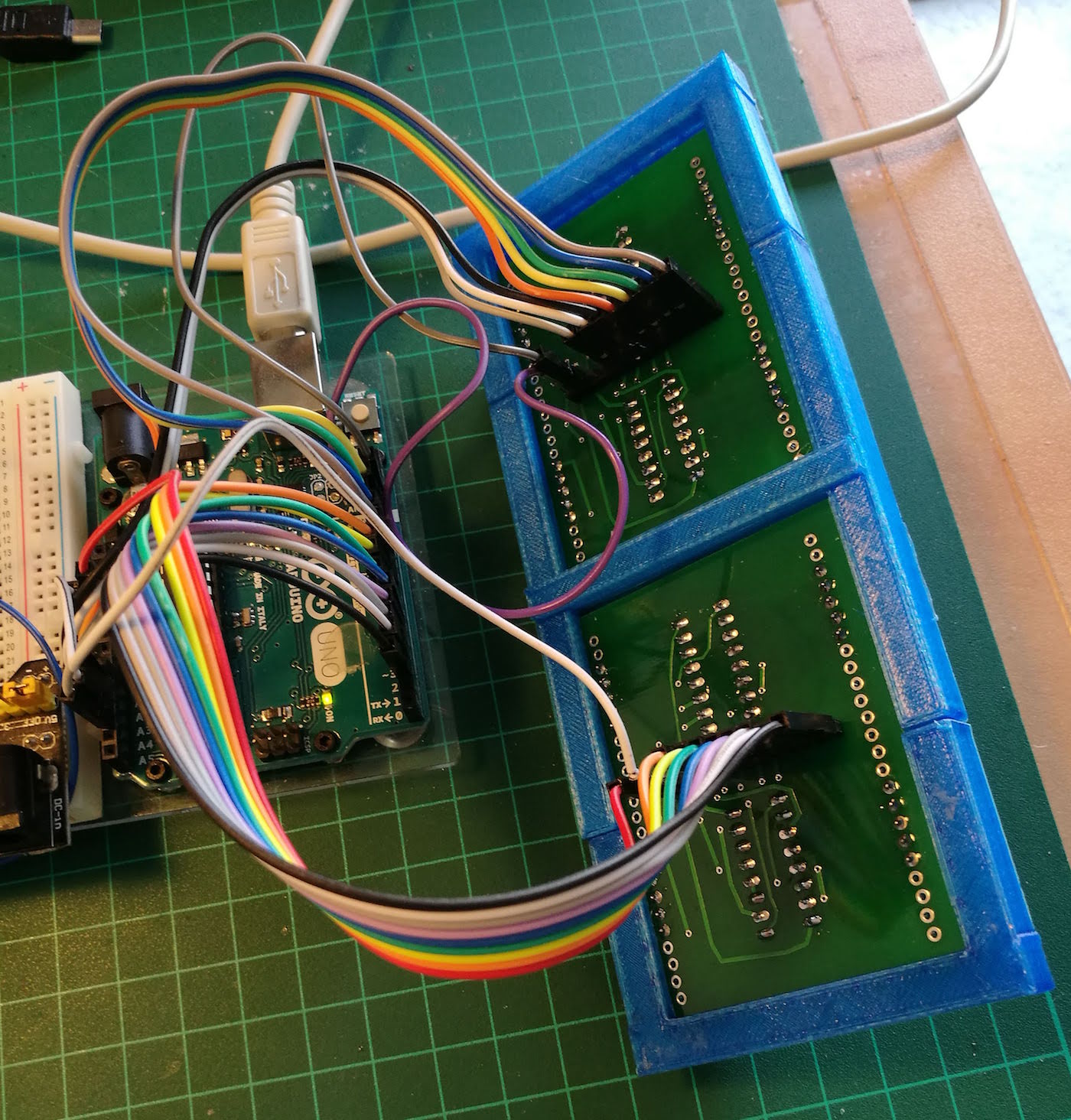
(The photo shows two boards with a basic 3D-printed frame to hold them together. As you can see, with the headers in place, there's room for all four 7-segment displays).
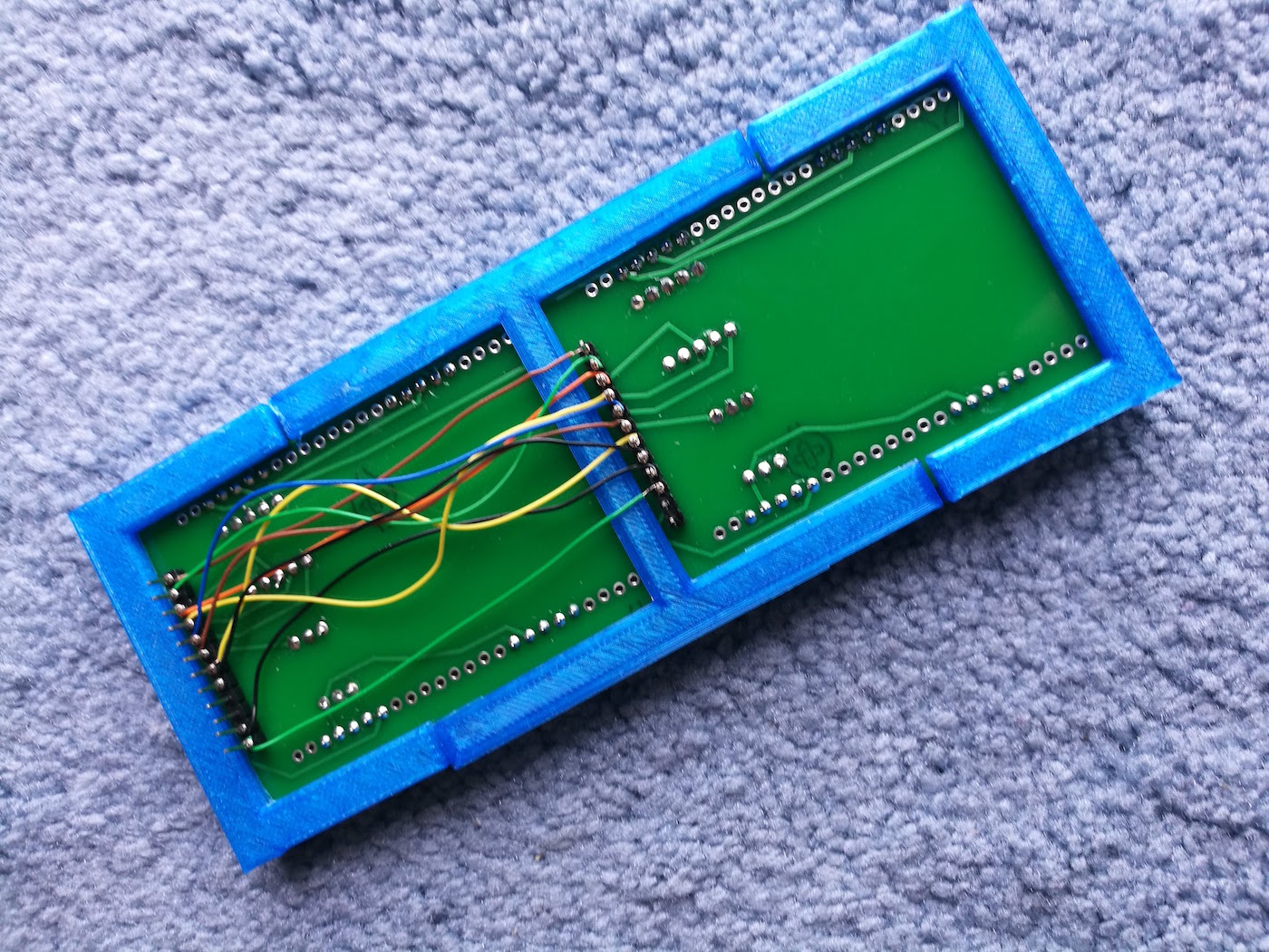
My next step was to connect the pins from both boards together. (Each board contained only two of my four 7-segment displays). This I did with simple wire wrapping.
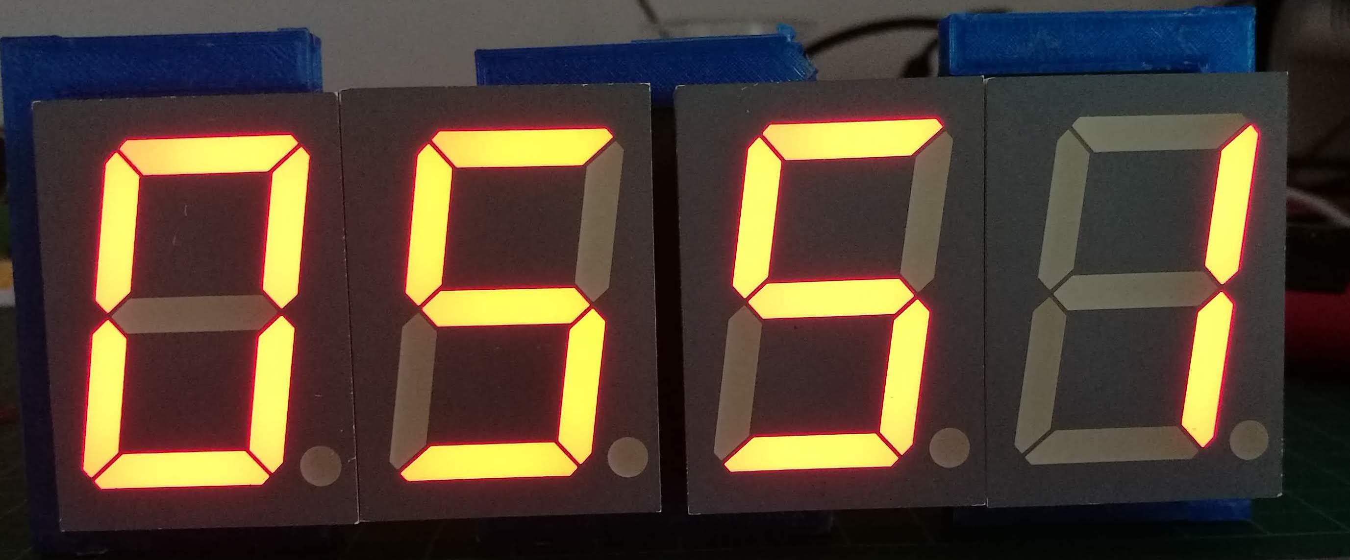
Did it work?
When I connected my Arduino to the side header pins and ran the multiplexing software, the display burst into life. All four LEDs flashed their digits.
I wasn't happy
One of the problems with multiplexing is that you're driving the Arduino hard, flashing segments on and off so rapidly, the eye can't catch it. I don't know if this was the reason, but I wasn't happy with the brightness of the digits. They were barely visible in daylight.
Getting to the decoder
As the MAX7219 wasn't suitable, I went looking for a common anode alternative. I came across the SN74LS47N. I'd never used a decoder before and didn't know what it was.
It was while I was learning how to use it that I discovered binary output from an Arduino. Playing with binary took me on a different path - and prompted me to write the blog post about making an Arduino Binary Counter.
If you're intending to use the SN74LS47N, please refer to the explanation given in the post above because I'm sticking to the hardware here.
New PCB
So, now that I'd figured out how to use a decoder, it was time to make a new PCB. It started out looking like this:
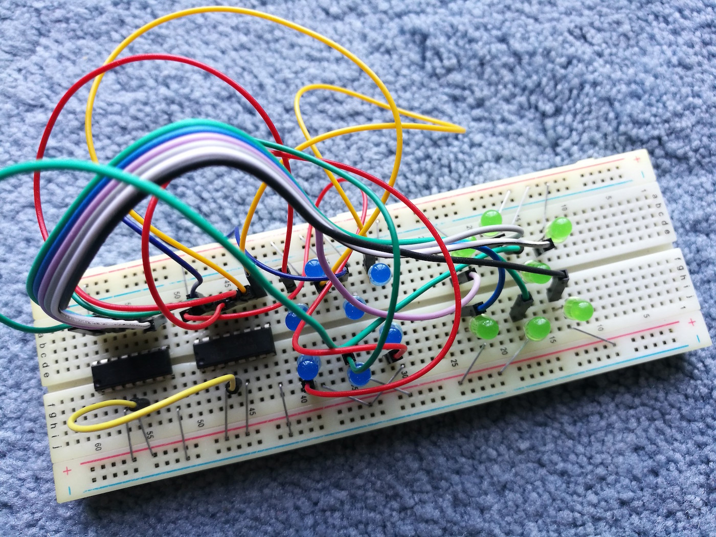
As you can see, it's a mass of wires. I didn't have a small common anode 7-segment LED, so I used regular LEDs instead. If you look carefully at the board you can see that to cut down on wires, I used staples for the GND and 5v rails. (Had I not, it would have been impossible to work with.)
From the working breadboard, I moved over to Fritzing. There I produced this:
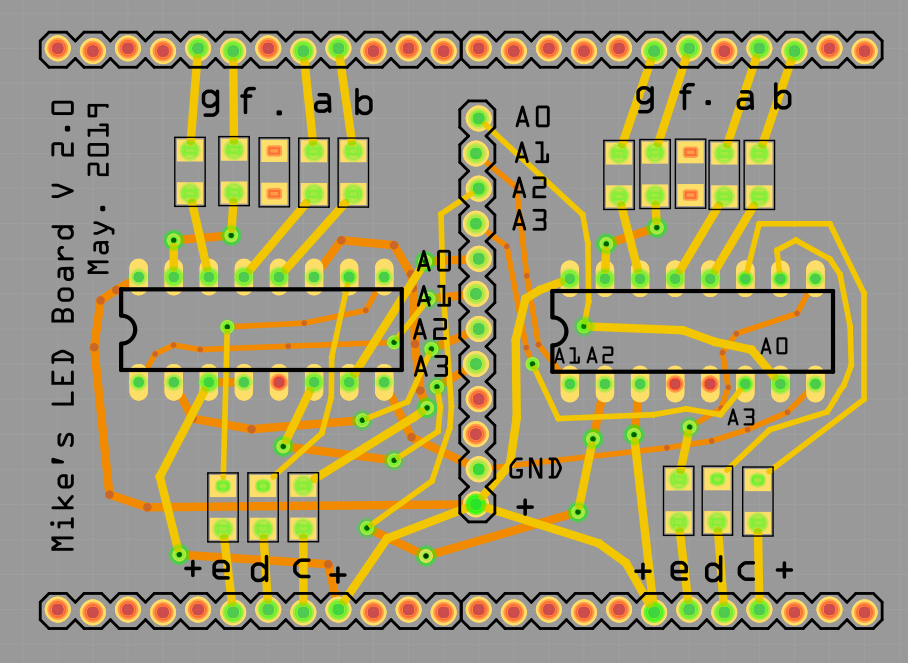
Again, my trace work is terrible, and co-blogger, Allan was appalled. After I'd already sent it for manufacture, he re-did the board, producing this - but it was too late because my boards were already in fabrication. (Don't know why one of his chips is bigger than the other.)
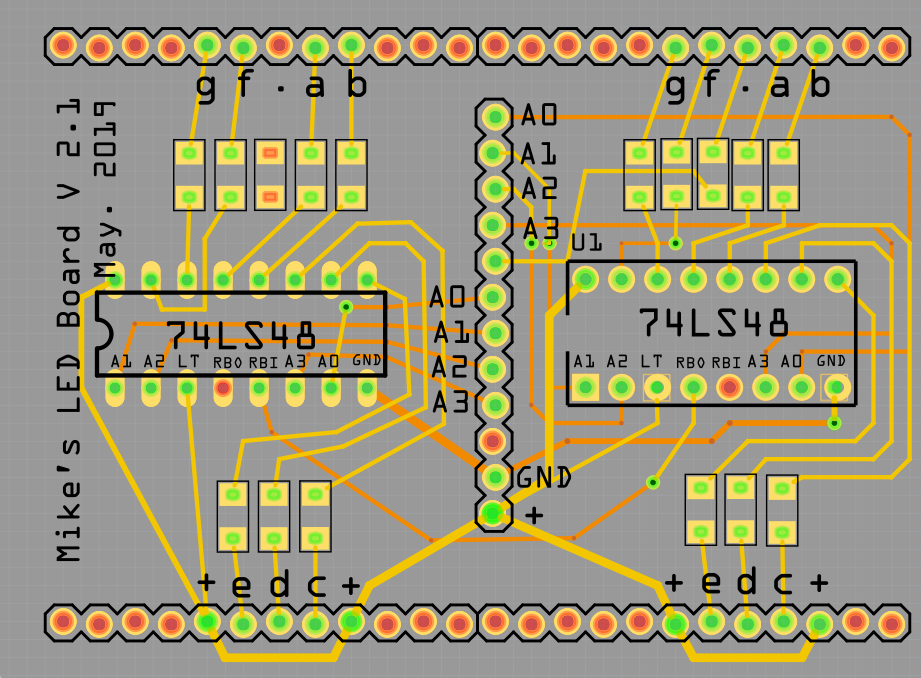
I admit, I learned from Allan's version, and as you'll see, my next board was much less cluttered.
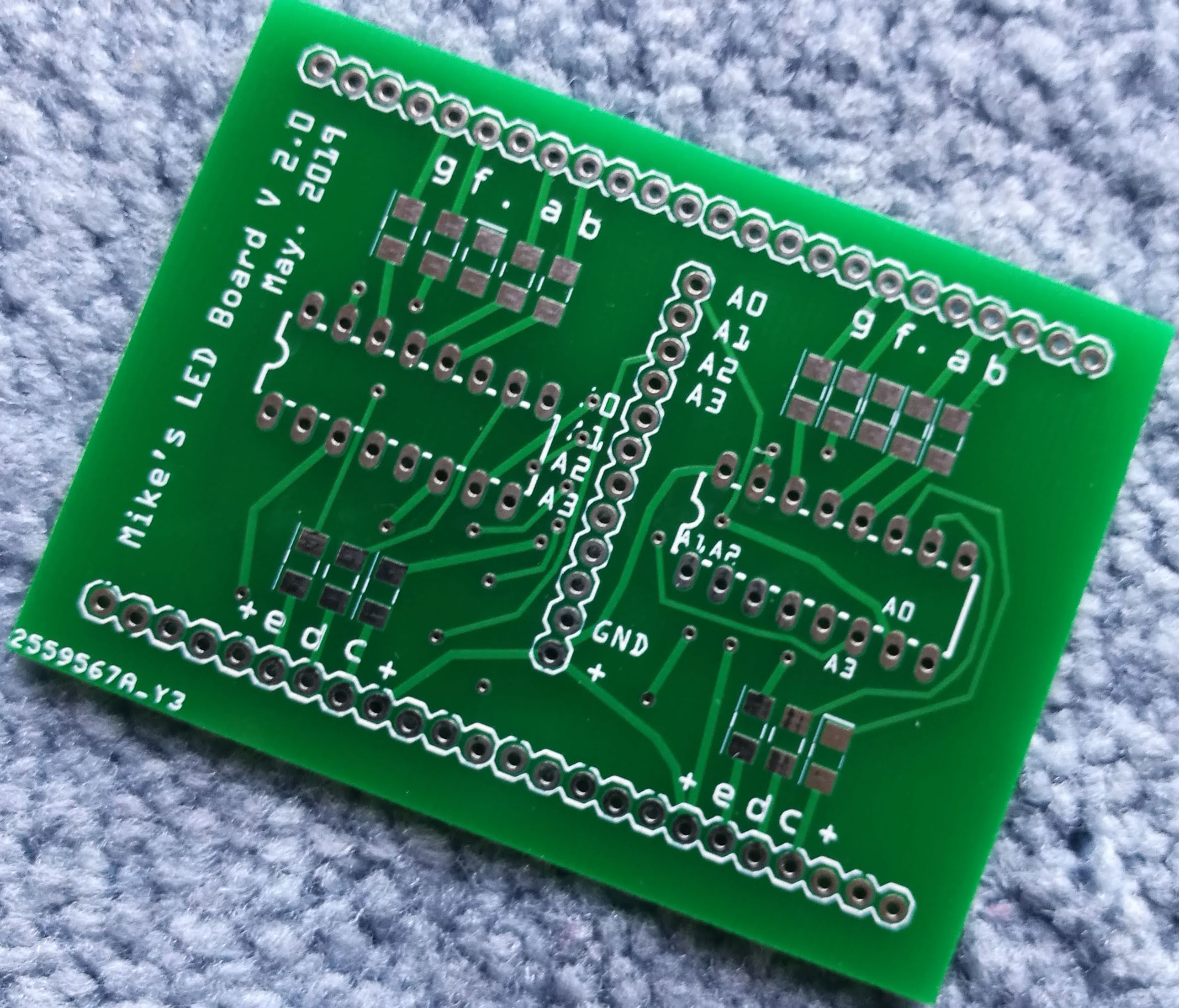
A couple of weeks later, my boards arrived from PLCPCB.
I soldered on the electronics... Notice, I moved over to SMD resistors to make the board neater.
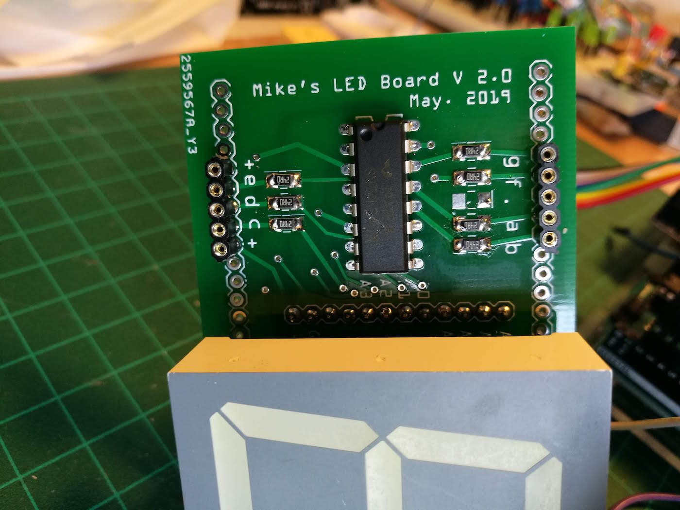
...then connected it all together.
The result was spectacular:
Still too many wires
Having successfully created two decoder boards, I was nearly there, but looking at the setup, there were still dozens of wires connecting the Arduino to the boards.
And I was running it from an Arduino Uno. My intention had always been to work with a cheap Chinese Nano.
Feeling more comfortable at designing boards, back I went to Fritzing. This time I designed a connecting daughter-board that incorporated the Nano. I took some lessons from Allan's improved design of my decoder board, using thinner traces, less vias, and straighter, less angled lines.
Once again, PCLPCB excelled at production and delivery. The boards arrived at the other side of the world 10 days after I uploaded the files.
With all components attached, the daughter board connects the encoder boards to the built-in Arduino Nano.
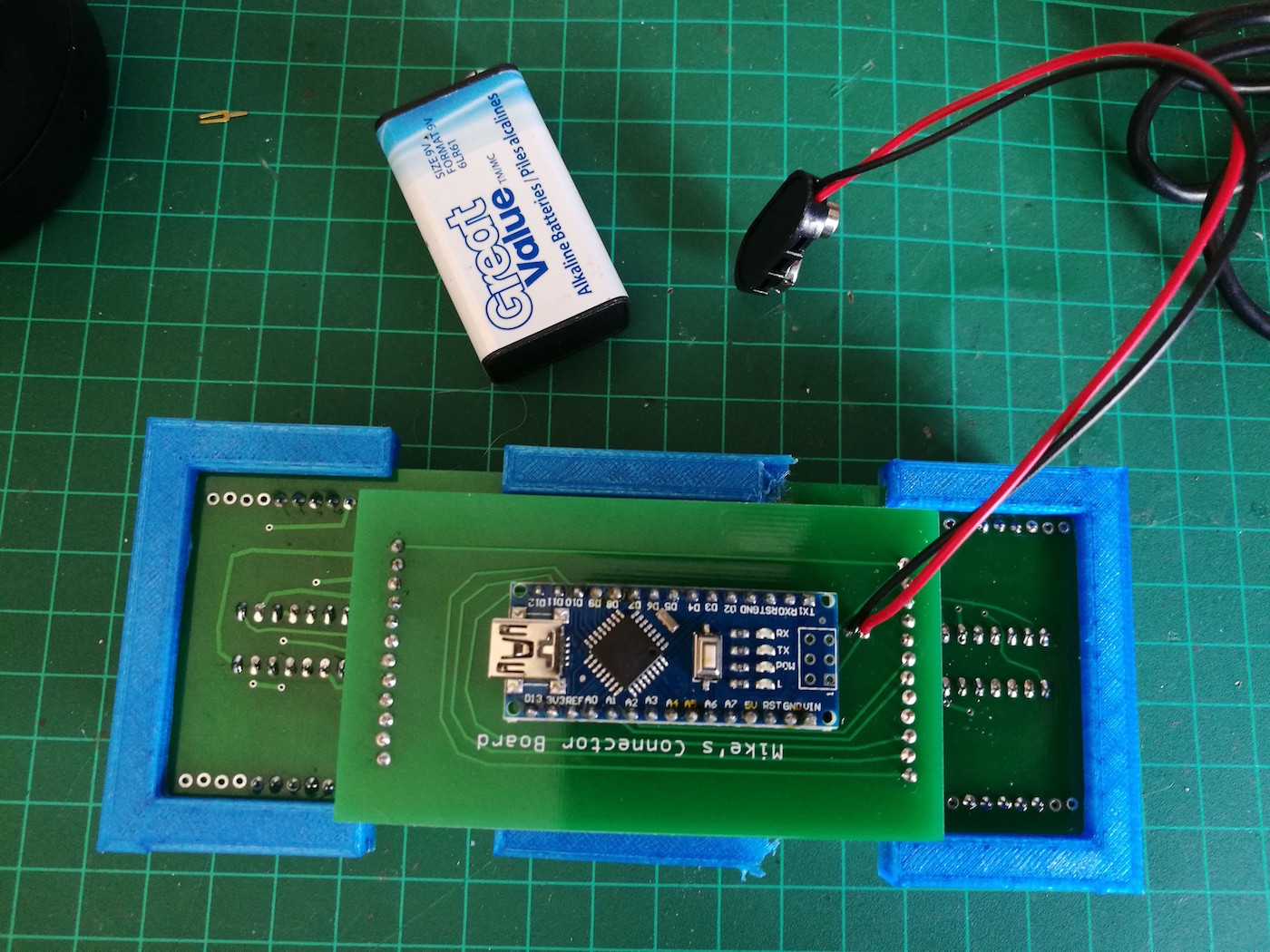
I'd incorporated a power point to attach a battery to the Arduino's Vin.
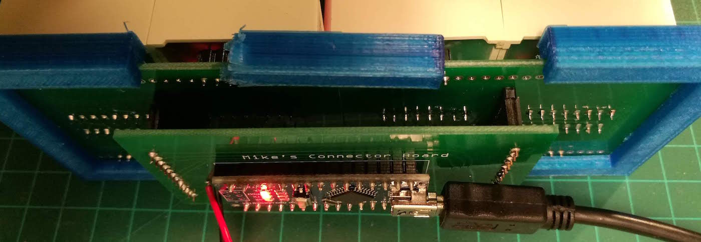
The working product
Case and Software
When I get around to making a case for my creation, I'll post a photo here.
As for the software - well, now that I have the hardware set up and attached to an Arduino, I can program it to do anything - from a clock to a timer, from a subscription-counter to a temperature display.
I'll experiment with sketches and post them when they're working.
Conclusion
My goal in documenting this process was to illustrate that even a beginner like myself can create amazing things by taking small steps, watching YouTube videos, playing around, and experimenting.
If anyone had told me before I started this project that I'd have a working 3.8cm 4-digit display neatly packaged on custom-designed PCBs without a single trailing wire, I wouldn't have believed them. Yet, her it is.
Not so long ago it would have taken a huge effort to create a custom-built PCB to do this, but with today's technology and the small price of PCB manufacture, it turns into something anyone can do.
Post Ends Here
Current-Limiting Resistors
To protect the circuit, current-limiting resistors are a must when working with LEDs. So, on the breadboard I needed to add a resistor for each segment.
My datasheet says that each LED segment is 20mA, so which resistor should I use?
Here's the formula:
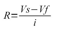
R is the resistance. Vs is the supply voltage (the voltage from the Arduino pin). Vf is the forward voltage drop - obtained from the datasheet.
My datasheet says the forward voltage of each LED segment is 3.7v. Some simple arithmetic and I have my resistor value - 25 ohms.