A couple of days ago I watched a YouTube video where a guy pointed a device at a spinning disk. The disk's rotation speed was displayed on the gadget's screen. When the speed changed, the reading changed with it.
At first I didn't understand how it could read revolutions per minute (RPM) by just taking an instantaneous reading. (In my naivety I assumed a minute had to pass!)
I began to wonder how it worked - and whether I could make a rotation speed meter with an Arduino.
It seemed daunting, but the more I thought about it, the easier it became. As it turned out, it's one of the simplest projects I've done so far - with surprisingly good results.
Here's how it's done.
The Principle
The theory of how it works is very simple. Light reflected off black and white surfaces varies. All we need to do is count these variations as an object spins.
For my prototype I took a strip of paper and glued it around the circumference of a cylinder attached to a small 5v motor. One side of the strip I left white, the other side I coloured with a black marker.
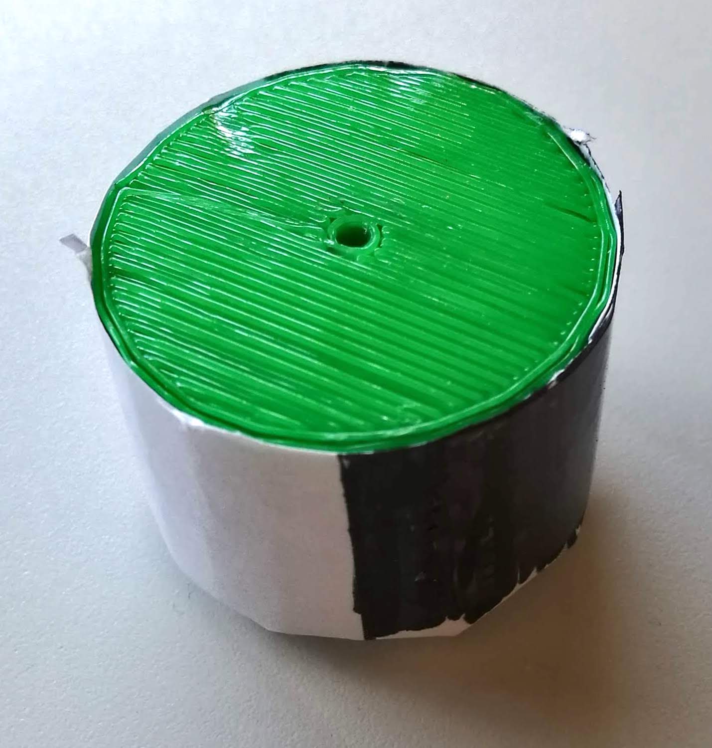
The idea is to shine a light on the rotating cylinder. When the white paper is facing the light, it will reflect a certain amount of light. When the black side is facing it, the reflected light will decrease. The light is sensed by a Light Dependent Resistor (LDR) which changes its resistance accordingly. By counting the number of times the resistance changes in a set time period, it's possible to calculate the number of rotations, and hence the speed of rotation.
Watch the LDR carefully in the following video. (Just below the light source.) You'll see the light falling on it changing rapidly.
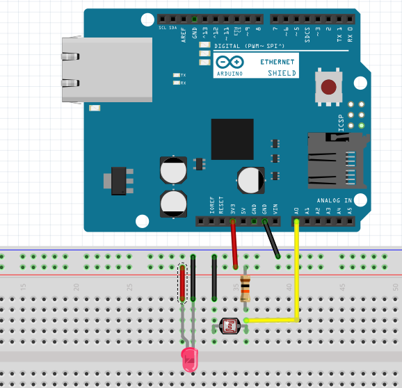
The circuit
There's not much to the circuit. The only thing you need to be aware of is that to properly read the LDR on the Arduino analog port, it'll need to be part of a voltage divider. This means adding a 10k resistor.
The Code
The code is only a few lines. The LED is permanently on, so doesn't need to be controlled. The LDR is connected to A0 (an analog pin) and a reading taken.
I set a counter to zero. (RotationCount).
For testing, I set a delay of one second so that I could see the resistance of the LDR with light reflected by the black and white surfaces respectively. Once I noted the difference, I set the
threshold_val
so that the RotationCount would increase by one each time the resistance of the black was registered. If it stayed on white, the counter would not increase.
Once I'd established the threshold_value, I took out the delay as I needed the Arduino to register resistance changes at high speed.
int LDR = A0;            // LDR input at A0 pin.
int LDRReading = 0;      // to store input value of LDR
int RotationCount = 0;   // to count rotations
int threshold_val = 100; // set threshold value of LDR. This will vary with your LED and LDR.

void setup() {
  Serial.begin(9600);     // initializing serial communication.
}
void loop() {
  LDRReading = analogRead(LDR);    // Reading LDR
  if (LDRReading > threshold_val)  // Varies with white and black. Set at value between the two
  {
    RotationCount ++; // Add one to rotation count
  }
  Serial.println(LDRReading);    // Print LDR Reading
  Serial.println(RotationCount); // Printing LDR count

// delay(1000);                      // use for testing LDR reading
}
So how do I know it's working?
On the Arduino serial terminal I watched with satisfaction as the count of rotations scrolled rapidly into the thousands, then tens-of-thousands. It was way too fast for me to actually read the numbers.
Observing the spinning cylinder with the naked eye, all I could see was a blur of grey as it rotated at great speed.
It was then that it occurred to me that the LDR may be seeing grey too - in which case it may have a constant resistance above my threshold - meaning it wasn't counting the rotations, just racing at the speed of the Arduino clock.
How was I to test this? How was I to find out if I was actually counting the rotations of the motor?
I thought of flashing the LED to create a stroboscopic effect. I could then vary the flash rate until I saw the motor "stand still" - from which I could calculate the rotation speed.
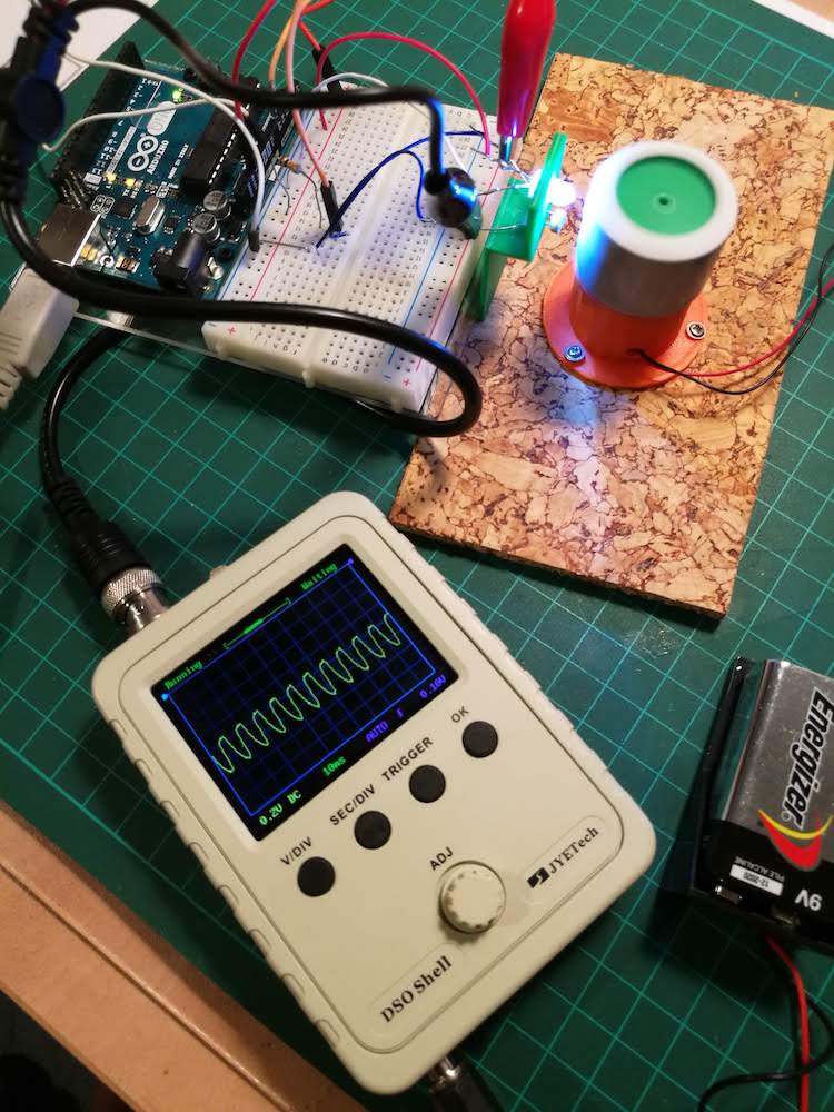
I was about to wire it up when co-blogger Allan suggested I use the little oscilloscope I'd constructed from a kit a few months ago. (There are a lot of reviews of this kit all over the web. If you're just a hobbyist like me, I can't recommend it strongly enough. Yes, it has only one noisy channel and yes, it can't register below a certain frequency, but if you just want to see if your Arduino (Raspberry Pi) pins are switching on and off, it's a brilliant little gadget. This project illustrates just how useful it is. It's also great fun to build!)
Following Allan's suggestion, I attached my probes to the legs of the LDR and turned the motor on. After a bit of fiddling with voltage and frequency, I got a fairly regular wave on the oscilloscope. According to my reading, I was getting a full 0.2v cycle every 10ms. In other words, something was making the voltage on the legs of the LDR go from zero to 0.2 volts every 10 milliseconds. (Indicating a rotation speed of 6000 RPM - 100 x 60). Was this just the regular clock speed of the Arduino, or was it actually counting the resistance fluctuations of the LDR?
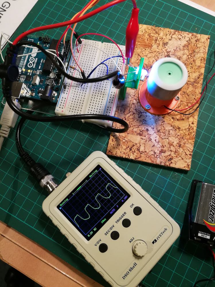
The way to find out was to vary the speed of the motor to see if my wave frequency changed with it.
I was amazed to discover that it actually did. When I slowed the motor down (it's a 5v DC motor taken from an old CD Rom tray), the frequency of the wave on my oscilloscope changed with it. This proved that I was actually counting the changes in resistance caused by varying light reflection as the cylinder rotated on the motor.
Nothing new
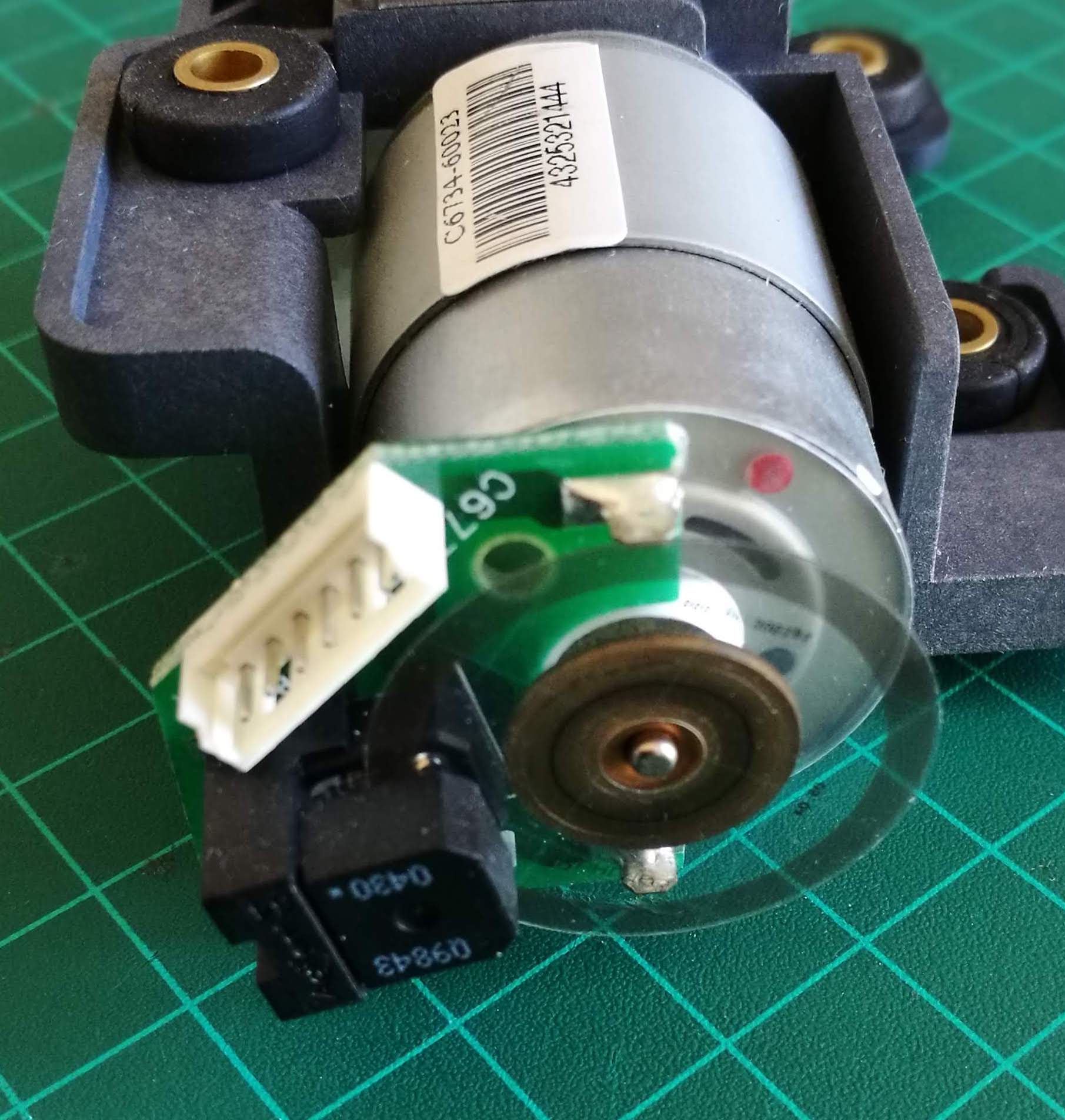
Of course, this principle is nothing new. Many motors in commercial devices have rotation sensors that use the same principle. Often, they have a plastic disk with very thin radial black lines. Instead of reflected light, the sensor detects when light passes through the disk and when it doesn't.
Still, it's satisfying to be able to produce such a device with just a few lines of code and two penny components. Naturally, my prototype would quickly run into trouble with a faster motor - as the clock speed for reading the LDR couldn't keep up with the changing values. But for educational purposes it's a great little project.
Next step
My next step is to add an LCD screen to display the RPM on a continuous basis. I'll document it below when it's done.