This is a continuation of the post I wrote more than two years ago where I explored the pin layout of a large LED dot matrix display.
As you can see from the photo below, I eventually made it into a clock/thermometer. The problem was, it had lots of wires running around as the Arduino had to connect to the LED Matrix and to the RTC module.
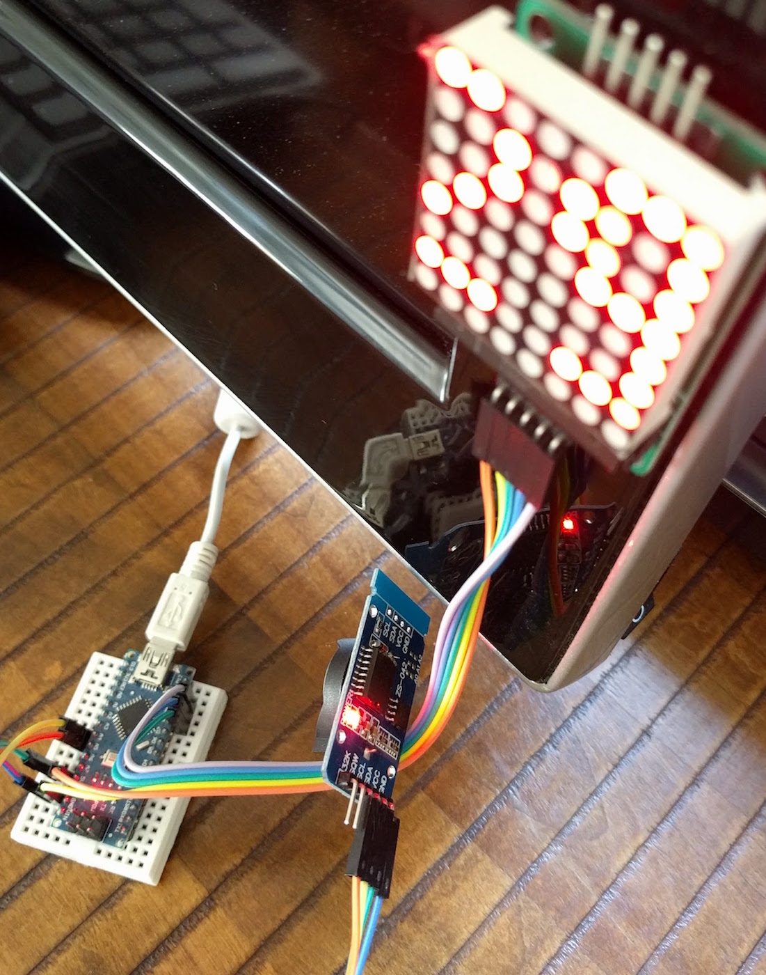
Significant Other put up with the mess of my wires for a while, but it really was a bit of an eyesore.
In the two years since I made the device, cheap and easy fabrication of PCBs from China has come a long way. So far - in fact - that even someone with very little knowledge of electronics can put together a functional device for the whole family to admire.
When PCBWay offered this site a coupon to make a board or two to help advertise their wares, this was the perfect opportunity to clean up some of the wiring of my LED Matrix clock.
Building like LEGO
I already had my device up and running and I had no intention of creating a custom board with installed discrete electronics. This could be done - probably quite easily - but I didn't have the time or energy to start from the beginning. Instead, I decided to make a "LEGO project." I'd take the existing boards and create a "motherboard" to attach them to.
Designing in Fritzing
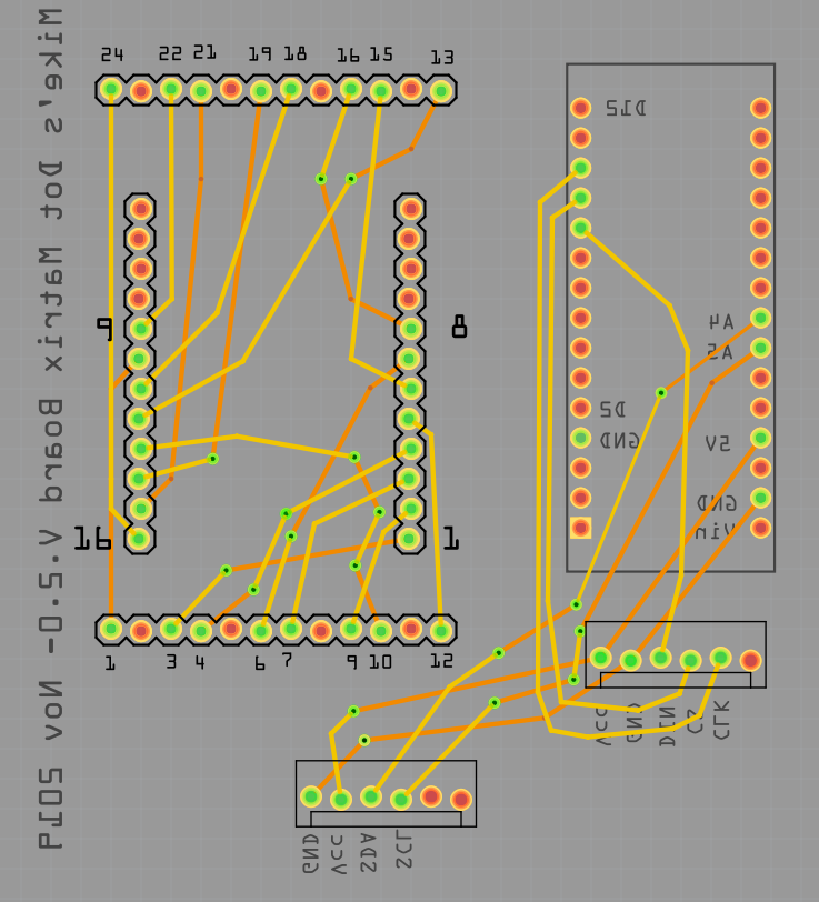
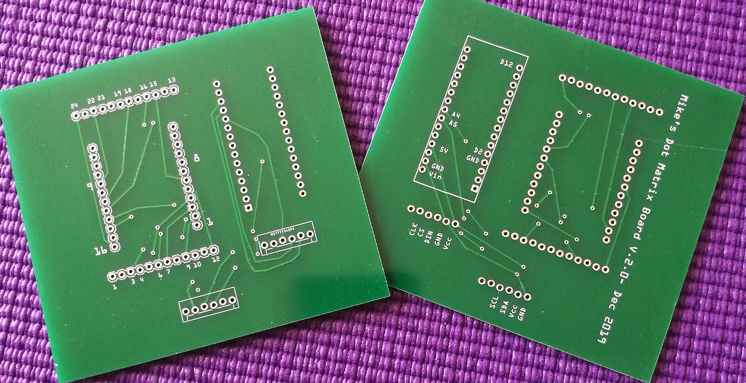
As usual, I used the board design tool in Fritzing. (Excuse my traces; I'm not an expert at this, and the aficionados among you will probably scoff.) As you can see, the board is just holes and traces. There are no components on it at all.
My intention was to attach the Arduino, the LED Matrix and the RTC to the same board to create a neat package with few trailing wires.
On the left of the board are two sets of headers. The horizontal headers, at top and bottom, would accept the LED pins, and the vertical headers would take the MAX7219 driver board. The Nano would be on the right, and the RTC would connect with wires to a header below the nano.
I labeled only a few pins - enough to help me position the components.
PCBway
PCBWay did a great job with the boards. Precision was very important as I had to attach the LED matrix to headers at a very specific distance apart. If they were slightly off, the LED wouldn't fit.
Fortunately, everything came positioned perfectly and the boards were exactly as planned.
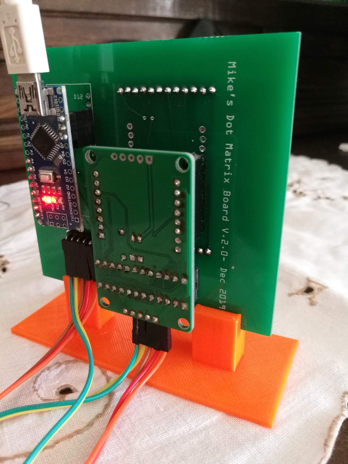
Two-sided
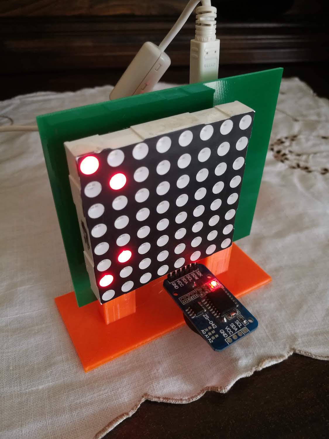
I wanted the LED at the front and the Arduino and Max7219 board at the back. To add some fun, I decided to position the RTC at the front, below the matrix.
This required me to put header pins on both sides of the PCB. The end result looks great and there are many fewer wires trailing around the project. I 3D printed a small stand and it now takes pride of place next to the TV.