The weakest link of our digital lives at home is the pipe into our house and the device it's attached to. Our cable-modem allows our equipment to communicate with the outside world.
Like all computers, modems are prone to crashing; some of us need to restart at least once a week.
Recently my modem began disconnecting once a day, and because I can't face the hassle of setting up a new one, I decided on a workaround.
If a sensor could detect when the modem disconnected, it could power-cycle by itself.
The project ended up being much simpler and cheaper than I expected.
Components
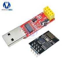
- ESP8266 01 - costs about $1.50 from Aliexpress.
- Programming board for the ESP. Some of us already have a programmer, but if you buy both together, you can get them for about $2.50.
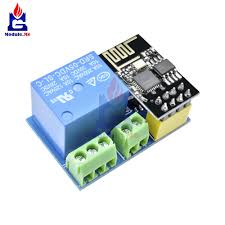
- A small relay board for the ESP. Search for ESP8266 5V 1CH Relay Module ESP-01. This also costs about a $1.
 .
.
How it works
In layman's terms, the process is simple. The ESP periodically pings Google through the modem. If it gets a reply, it does nothing; the relay stays closed and the modem stays on.
If the ESP does not get a reply, it will "understand" that the modem is down. When this happens, it turns off the relay, waits 30 seconds, then turns it back on, thus power-cycling the modem.
Infinite Loop
One flaw had me stumped for a while before I worked it out.
We all know that it takes the modem a few minutes to successfully "handshake" with the line. When I first set up my device, the ESP kept pinging Google during setup. As the modem hadn't yet connected, the ESP got no reply - so did a power-cycle. I was in an infinite loop getting nowhere.
I needed the ESP to give the modem time to successfully handshake. Once this happened, the ESP would enter its regular polling of Google.
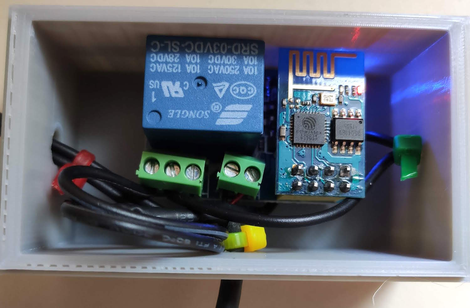
Connections
The relay sits in the middle of the router's power cable. It's switching only 12v so there are no safety issues involved. The only setback is that the ESP relay board also needs power - which I've given it through an old 5v, 1A cellphone charger. I printed a small box to put it in but decided not to cover it to prevent overheating.
Afterthoughts
Since I installed the device, it has worked flawlessly. However, I see my disconnects are becoming more frequent and I'm wondering if my router is going to need replacing sooner than I thought. To obtain more details of how often it power-cycles, I'm working on a version (with co-blogger, Allan) that will:
- Alert me when it does its thing and
- Logs the time, dates and frequency of events.
This entire project got me thinking; why is this not built into routers? I'm sure it would be very easy to tell a router to power-cycle if it loses internet connection.
Allan's Technical Discussion
Programming genius and fellow nerd Allan Schwartz provided me with the following discussion about the code we installed on the Arduino:
Our solution can best be described as an event-driver finite state machine.
In this application we have exactly 3 states:
- Testing State
- Failure State
- Success State
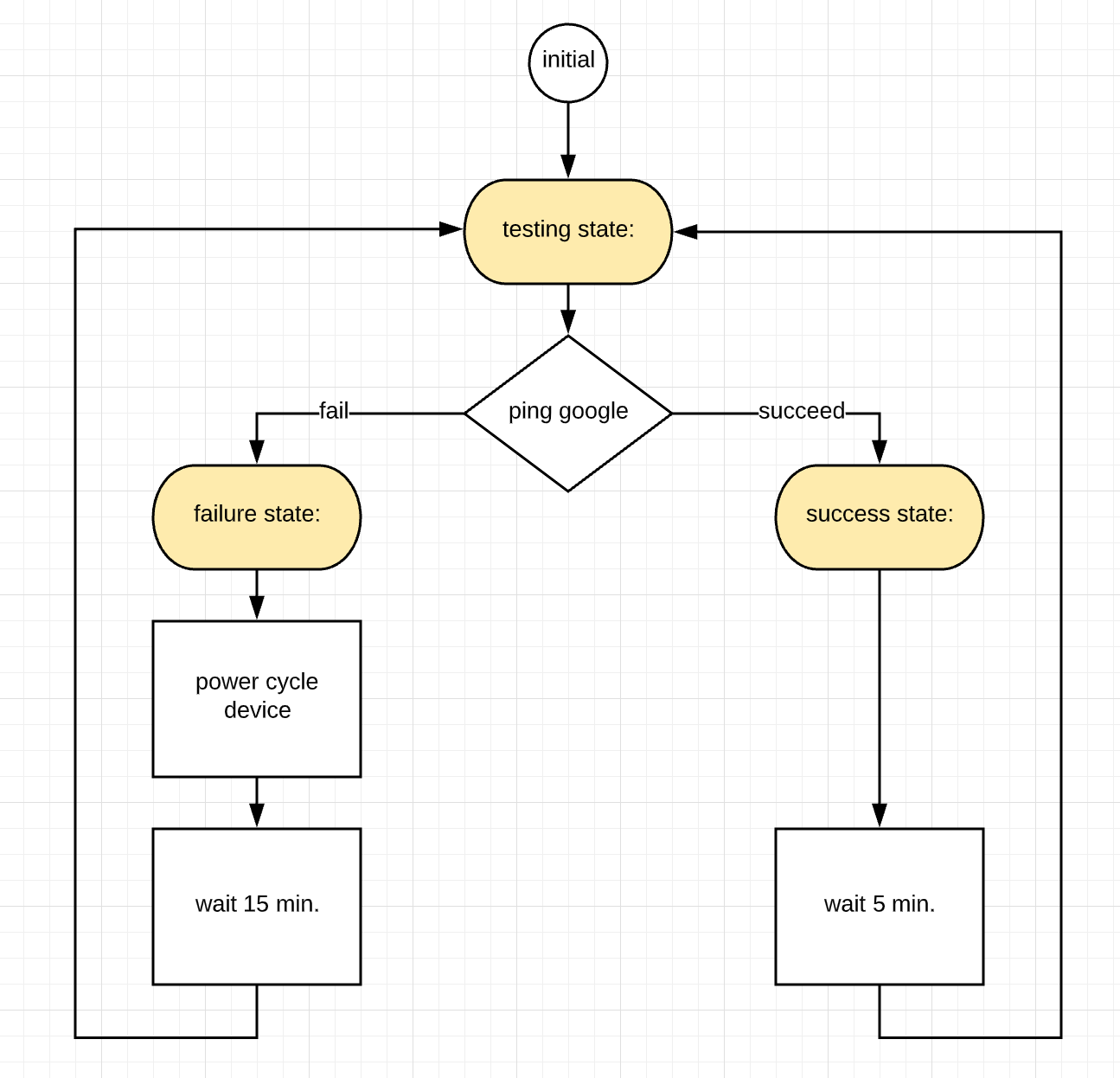
What the program does during each of these states is best described in the following State Diagram, a kind of flowchart. This is formally called a UML State Diagram.
The State Diagram shows the three states highlighted in yellow, and state transitions:
We can translate this state machine and the implied logical flow into Arduino C very accurately, so the intent of the C code is very clear, and we can check that the C code matches the logical flow exactly.
We start with an enumeration of the states. And a state variable CurrentState containing the initial state:
enum {
    TESTING_STATE=0, FAILURE_STATE=1, SUCCESS_STATE=2
};
int CurrentState = TESTING_STATE;
Then, the loop() function has a switch statement that handles each state as a case.
void loop() {
    switch (CurrentState) {

        case TESTING_STATE:
            if (!WiFi.hostByName(Hostname, HostIP))
                CurrentState = FAILURE_STATE;
            else
                CurrentState = SUCCESS_STATE;
            break;

        case FAILURE_STATE:
            reset_device();
            delay(RESET_DELAY);
            CurrentState = TESTING_STATE;
            break;

        case SUCCESS_STATE:
            delay(PROBE_DELAY);
            CurrentState = TESTING_STATE;
            break;
    }
}
State transitions are done by assigning a new value to CurrentState, then “breaking” out of the switch statement. Replacing the break with return would result in the exact same behaviour, because loop() is called continuously.
The Sketch
#include ESP8266WiFi.h

const char* ssid     = "yourssid";     // Your ssid
const char* password = "yourpassword"; // Your Password
const char* testHostname = "www.google.com";
IPAddress HostIP;
unsigned int localPort = 80;
const int RELAY_Pin = 0;               //Relay Pin

#define MINUTES (60L * 1000)
#define SECONDS  1000
const unsigned long  PROBE_DELAY = 5 * MINUTES;
const unsigned long  RESET_DELAY = 15 * MINUTES;
const unsigned long  RESET_PULSE = 30 * SECONDS;
int  Nreset_events = 0;

enum {
    TESTING_STATE=0, FAILURE_STATE=1, SUCCESS_STATE=2
};

int CurrentState = TESTING_STATE;


void setup() {
    pinMode(RELAY_Pin, OUTPUT);

    Serial.begin(115200);
    delay(10);
    Serial.println( __FILE__ );
    delay(10);

    // Connecting to a WiFi network
    Serial.print(String("Connecting to ") + ssid);

    WiFi.begin(ssid, password);

    while (WiFi.status() != WL_CONNECTED) {
        delay(500);
        Serial.print(".");
        delay(500);
    }
    Serial.println("\nWiFi connected");
}

void reset_device() {
    // keep track of number of resets
    Nreset_events++;
    Serial.println(String("\nDisconnected... resetting - ") + String(Nreset_events));
    digitalWrite(RELAY_Pin, HIGH);
    delay(RESET_PULSE);
    digitalWrite(RELAY_Pin, LOW);
}

void loop() {
    switch (CurrentState) {

        case TESTING_STATE:
            if (!WiFi.hostByName(testHostname, HostIP)) {
                CurrentState = FAILURE_STATE;
            } else {
                CurrentState = SUCCESS_STATE;
            }
            break;

        case FAILURE_STATE:
            reset_device();
            delay(RESET_DELAY);
            CurrentState = TESTING_STATE;
            break;

        case SUCCESS_STATE:
            delay(PROBE_DELAY);
            CurrentState = TESTING_STATE;
            break;
    }
}