EDIT (23/4/2015): We've added a toturial of how to flash the ESP8266 with the arduino IDE. As part of this toturial we've created a working code to control the water heater. If you plan to build a smart-house gadget check it - It'll make your life easier.
EDIT (24/3/2015): Hey! We opened a Facebook page! If you enjoyed this project "Like" us to follow new posts and projects - we promise not to spam :)
WARNING: This project deals with high voltage electricity. Do not attempt to build this project unless you are familiar with the safety measures needed to be taken care of. This project was done using the help of authorized professional person. In most countries you are not allowed to touch your home electric network if you don't have the proper authorization and certification. Don't get upset - you can still get a lot of information about the ESP8266 by reading this post.
Last week I've finally received this ESP8266 all the maker society is talking about. Also this week, it has been really cold around my area, which is not very common. During this week, one of the most annoying things are forgetting to turn on the water heater for the shower. It was pretty obvious what the project would be - a water heater (boiler) controlled over the net.
To be honest this project isn't new to me. Last year (On my pre-blogging area), I've already built a control for the water heater, but using an arduino micro-controller and NRF24L01 module. This way I could control the water-heater using another arduino with NRF24L01, and by connecting one of them with Ethernet module it could be controlled over the net as well. I could have used WiFi module but it was too expensive gadget in my opinion (about 40USD). The overall cost of the arduino project was about 10USD for the station connected to the net and 10USD for every other "slave" station (I had more than one).
And then came the ESP8266 module. What is the ESP8266 module? In short, it is a WiFi module with serial support which costs only 3USD-4USD. What even greater about this module is that it actually has a 32-bit 80MHz micro-controller inside, much more powerful than ATMEGA328 arduino (8-bit, 16MHz).
What you need to this project:
- ESP8266 module
- LM1117 voltage regulator
- 5VDC / 110AC-30A Relay or even better: a 3.3VDC one.
- Some electronic parts:
- Led
- npn transistor 2n2222
- 2x Resistors
- Capacitor
- TTL / FTDI / Arduino / Any device with USB-to-serial module
- AC/DC 220/110ACV to 5DCV or any cell phone charger
- A water-heater clock (Not must but at leasy you got to have a switch for manual use)
The list is pretty short, mostly because the ESP8266 module has almost everything you need inside.
Getting Started
So you got your ESP8266. Most projects I've read about so far involved connecting the ESP8266 with an arduino and used the serial interface to communicate with it by sending "AT" commands which comes with the default firmware of the ESP8266. The more challenging way, but also way more efficient, will be to write the entire program on the ESP8266 micro-controller. Some great guys made this special firmware, NodeMCU, that runs a very light operation system on the ESP8266, which provides two cool abilities: Handling a file system and running lua scripts. So the first step in order to build this project will be flashing the NodeMCU on your ESP8266 module. In order to do this I suggest reading one of two great post from our blog which will explain to you step-by-step how to do so - Windows users or Linux users. The steps are very easy, even if you are a windows user, I promise! When you are done, the ESP8266 is ready for the coding and the hardware.
Connecting and Coding
Now when we have the new firmware, we can simply connect the ESP8266 to the computer through a serial interface, and send commands such as open/delete file, write to file, run file, etc.
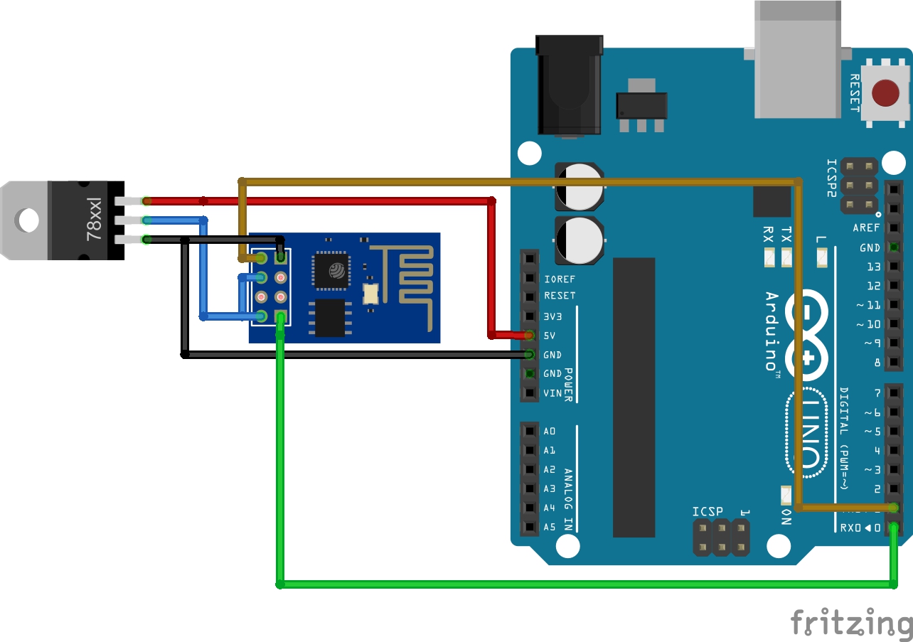
The ESP8266 needs 3.3V to operate so when connecting it to the computer, either through FTDI or an arduino you should use a voltage controller from 5V to 3.3V. Both the FTDI and the arduino usually have 3.3V output but the ESP8266 sometimes needs a lot of current ("lots" meaning around 200-250mA) and the output of those devices cannot give this amount of current. A sketch of the connections will look like that:
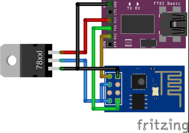
or with arduino UNO:
The easiest way to communicate with the ESP8266 is to open Putty, select the right COM and start writing. It will be a bit frustrating since you have to write a line and end it with CTRL-J to send it to the ESP8266. For example, if we want to write a script which controls the relay we will start by removing any existing file and creating a new file:
file.remove("relay_server.lua")
file.open("relay_server.lua","w")
Now, if we want to write some lua script to the file we will write:
file.writeline([[status=0]])
file.writeline([[pin=3]])
file.writeline([[gpio.mode(pin,gpio.OUTPUT)]])
To close the file and run it we will write:
file.close()
dofile("relay_server.lua")
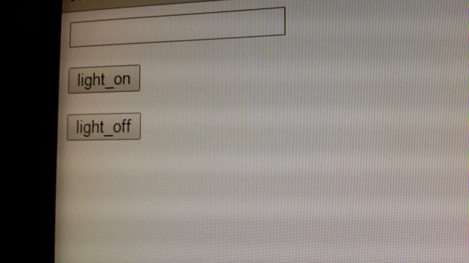
The full code can be found here. This is a short code which runs the "relay_server.lua" file, when the ESP8266 starts. This script config GPIO0 (one of the ESP8266 I/O) to be on output mode, then opens a server on the ESP8266 and creates two buttons for "ON" and "OFF" of the relay. When either of the buttons are pressed, GPIO0 changes its state. Here is a screen-shot of what you'll see on your browser when typing the ESP8266 ip address.
Before uploading your script you have to define your connection. It can be done pretty easily using some other lua commands:
wifi.setmode(wifi.STATION)
wifi.sta.config("SSID","password")
Another possibility is Use this script which will create a hotspot on first use (U/P: myhotspot/myhotspot), then connect to it from your phone/laptop. Check your IP - the hotspot IP will most likely be X.X.X.1 where the X's are the same as your IP. Type the hotspot IP in your browser and it will open a config window to choose your SSID and Password. After typing them it will restart and connect to your selected network. This is a very simple script - It will probably be more advanced in the future.
Writing using "putty" can be a bit frustrating. It means that if you got something wrong in the lua file you'll have to write it all over again. A great helpful python script, written by Notamacuser, can be found here. The script opens the selected serial port and write a chosen text file into the ESP8266 line by line as if you wrote it as explained before. If you are using windows and not familiar with python consider download Winpython, run its command line and run the script with the COM serial and the text file as inputs.
EDIT: Check this new post for more convenient methods to write LUA code to the ESP8266,
And this even newer post for flashing a program especially for this project using the Arduino IDE.
Hardware
The ESP8266 is ready with the right code, and all that left to do is to get a water heater timer (or switch), hack it and make it into a smart switch. Actually, if you got to this point, you can follow my instructions and use any electric device instead of the water heater and make your own smart house gadget (outlets, TV, AC etc.). If you need to disconnect any electrical devices from your home network, make sure you have the right authorizations or call a professional. Here is my water heater timer switch, on its back:
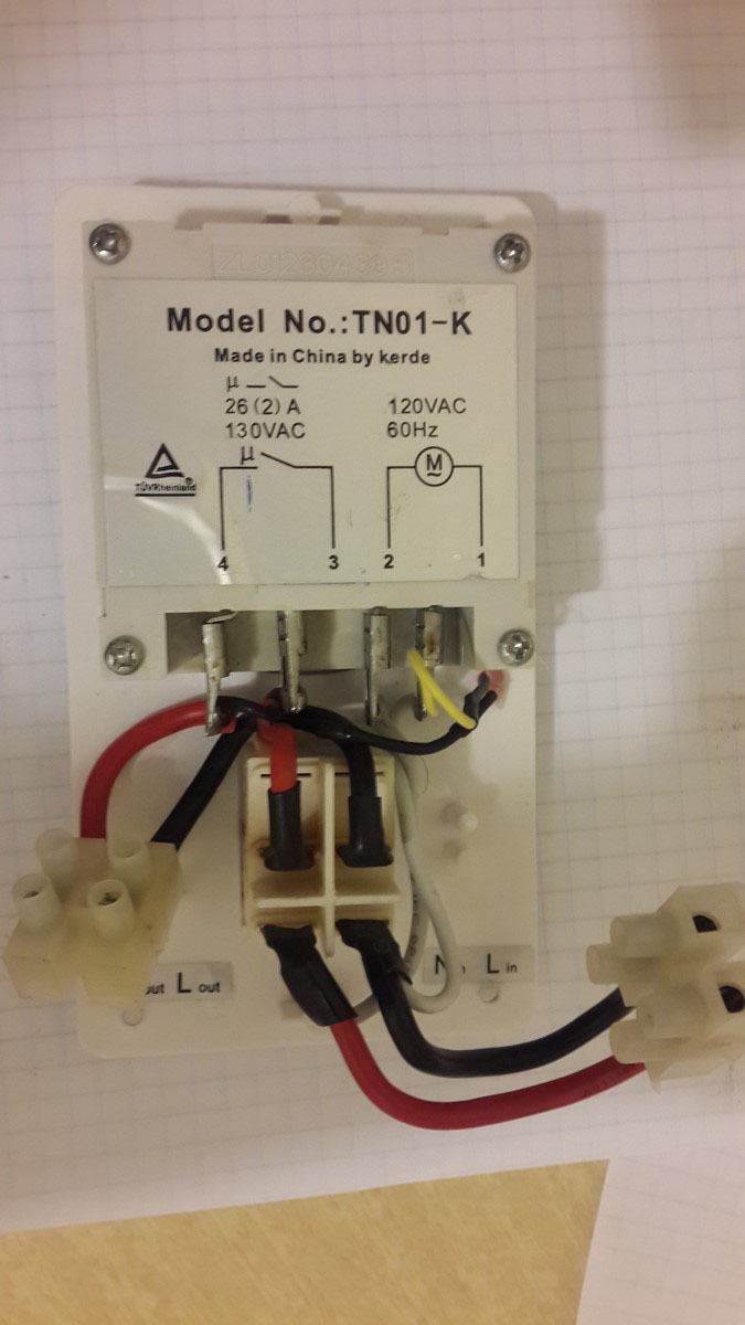
Note it has 4 wires. The two on the right are input Line and Neutral wires to power the gadget, make the clock work and lights on, and the other two on the left are outpout Line and Neutral wires, which means that when the circuit is closed (i.e. the switch is on and the timer sets "on" as well) the wires will be connected to the water heater and it will start to work. So the main architecture here will be to add a relay which, by changing its state, will "skip" the timer and close the circuit.
Powering the circuit
The ESP8266 needs 3.3V for power while all we have around us is 110VAC (or 220VAC if you are on the other side of the globe from me). One way is to use batteries, but it is not such a good idea since you can't make sure it'll work 24/7, and you'll have to change batteries all the time. The other option is to tear down a phone charger, and you'll get an electric circle which converts 110VAC to 5VDC and supply at least 500mA (which is much more than needed).
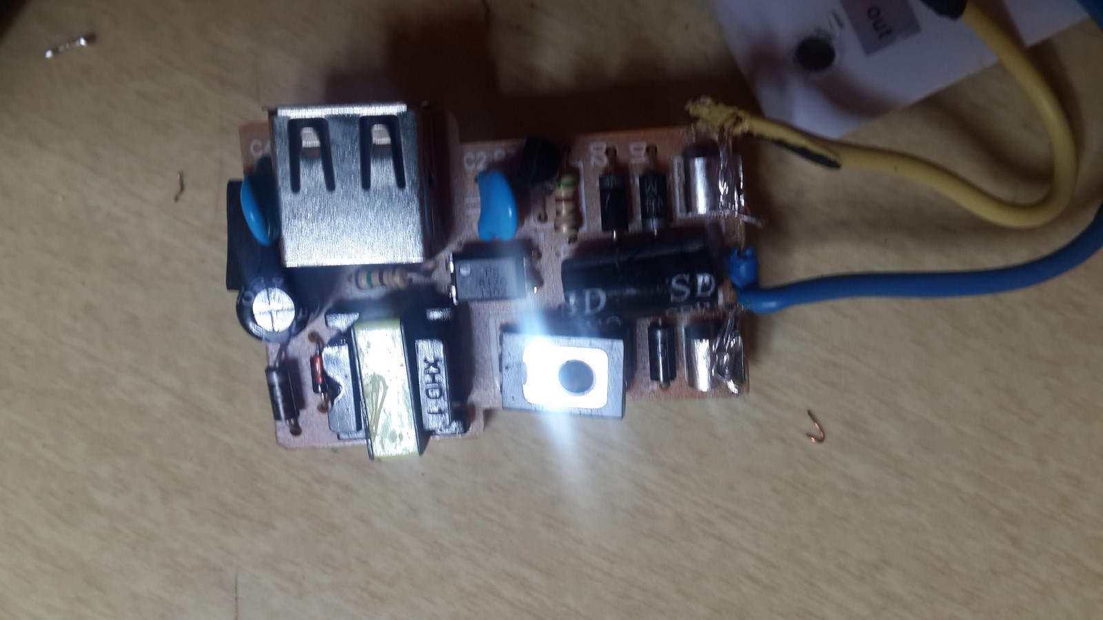
If we got 5V output, it means we are at the same spot where we were when we flashed the firmware on the ESP8266. We have 5V and using a voltage regulator we can drop it to 3.3V. I connected the AC part of the charger to two diagonal connections of the switch on the water heater, so when I turn off the switch I'll turn off the entire gadget, including the ESP8266 - That's a clever way to restart the module if needed.
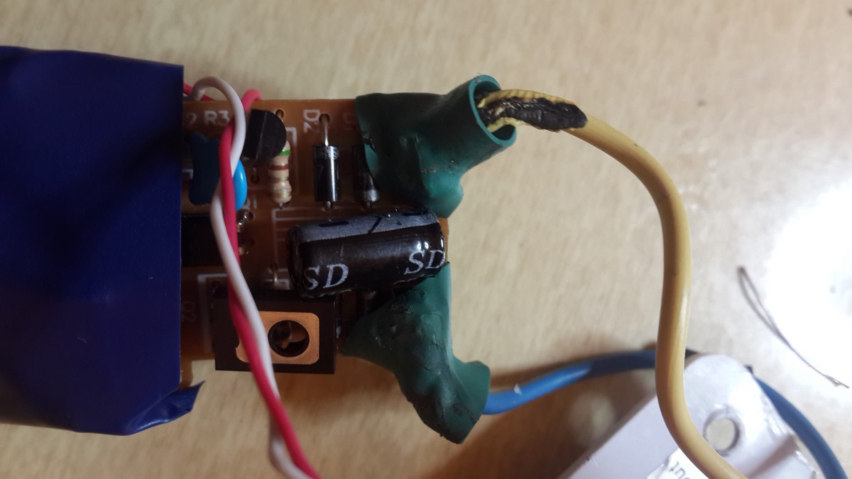
After connecting the AC connections, make sure to use heat shrinks so the wires won't be exposed.
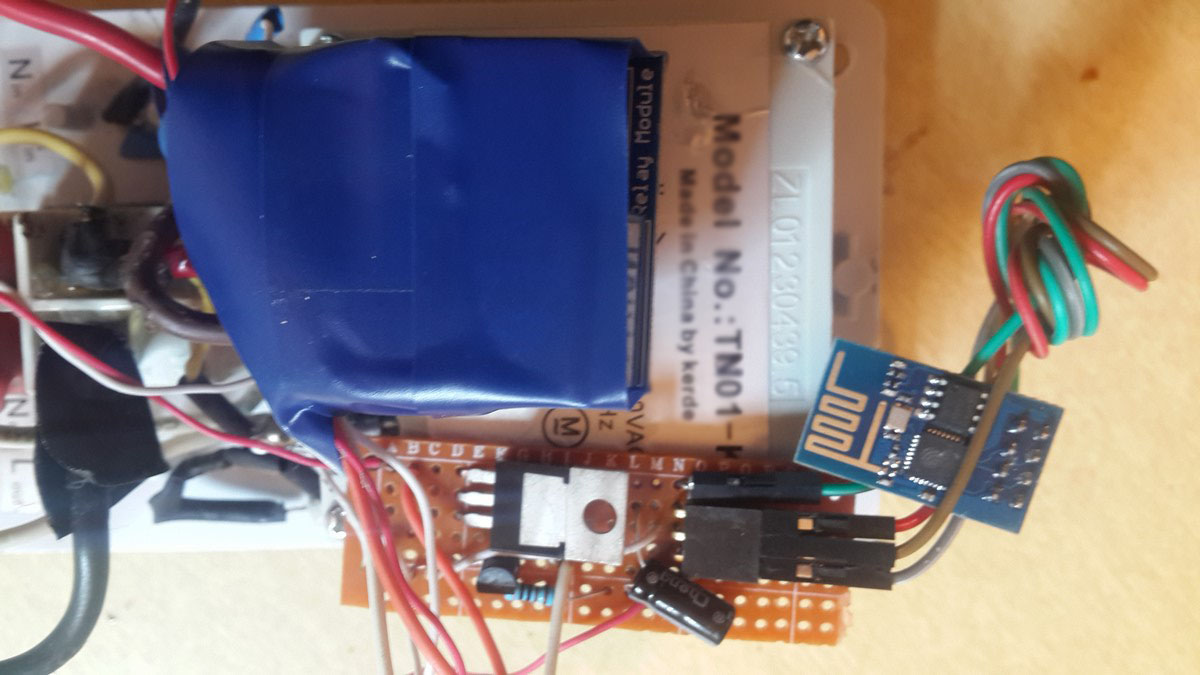
The Relay, ESP8266 and the rest
My water heater takes about 2700 Watts when it's on. This means that when it is connected to 110VAC it uses around 24.54 Amps. The frequent relay modules which I've seen on Ebay can usually handle 10 Amps, so especially for this project I got a 30A relay module.
The module has 3 AC connections:
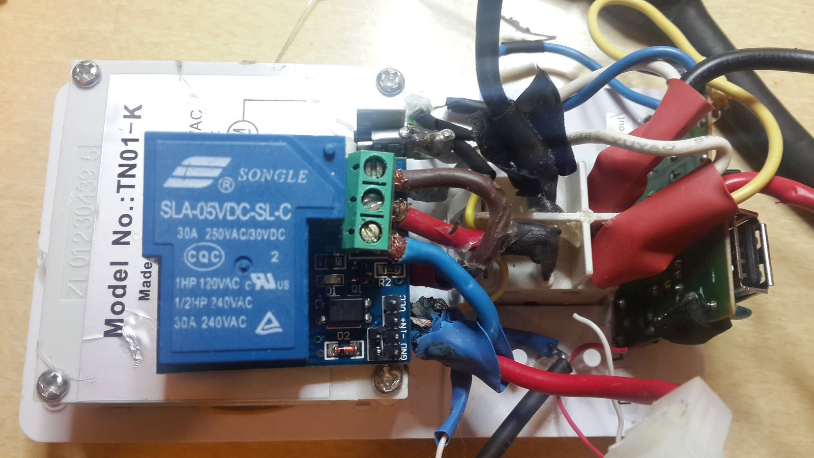
The middle AC is the input (COM) and it is connected to the output of the switch. The right AC is the "Normally Closed" (NC) output, and is connected to the input of the clock, therefore when this state is on, the gadget works as it worked before. The left AC is the "Normally Open" (NO) output, and is connected to the output of the clock, meaning when this state is on, we are "skipping" the timer, shortcutting the circuit, and turning the water heater on. On the DC side we have 3 pins, VCC and GND to power the module and IN pin to control the states (HIGH/LOW). While testing other relay modules I figured out that even though this is a 5V realy module, 3.3V can still control it and change its states. However, when it comes to the 30A module it needed more current than the ESP8266 GPIO can provide. I didn't find the datasheet of this module but in some forum I read it needs about 40mA while the ESP8266 GPIO can provide max of 12mA. This problem can be solved easily using a NPN transistor (A bit about transistors here if you want to read more). The solution is to connect the VCC and IN to 5V, but the GND will be connected to the collector of the transistor, the emitter to the ground, and the ESP8266 GPIO to the base through a resistor. That way, when the GPIO is not working or on LOW, the transistor will be closed and the relay module will not work, hence the state NC (Normally Closed) will be used. When the GPIO is on HIGH, the transistor will be open, the relay will work and will change the state to NO (Normally Open). The full circuit sketch can be seen here:
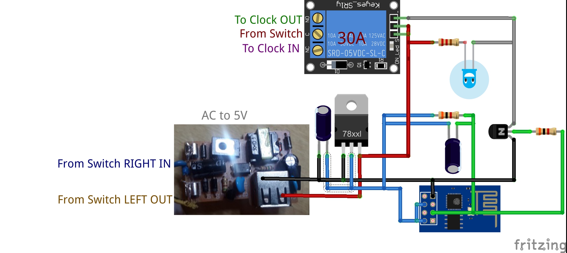
Two notes on the sketch which I had yet to explain:
A led and a resistor are connected in parallel to the relay, so when the water heater is working due to the relay, the led will work as well, just to let you know!
In case GPIO0 is connected to ground when powering the ESP8266, the micro-controller will enter to "flashing mode" (you probably notice this connection when you have flashed the firmware). In order to avoid this event, a capacitor is connected between 3.3V and the GPIO0, making a transient effect of 3.3V at the GPIO0 when powering the device.
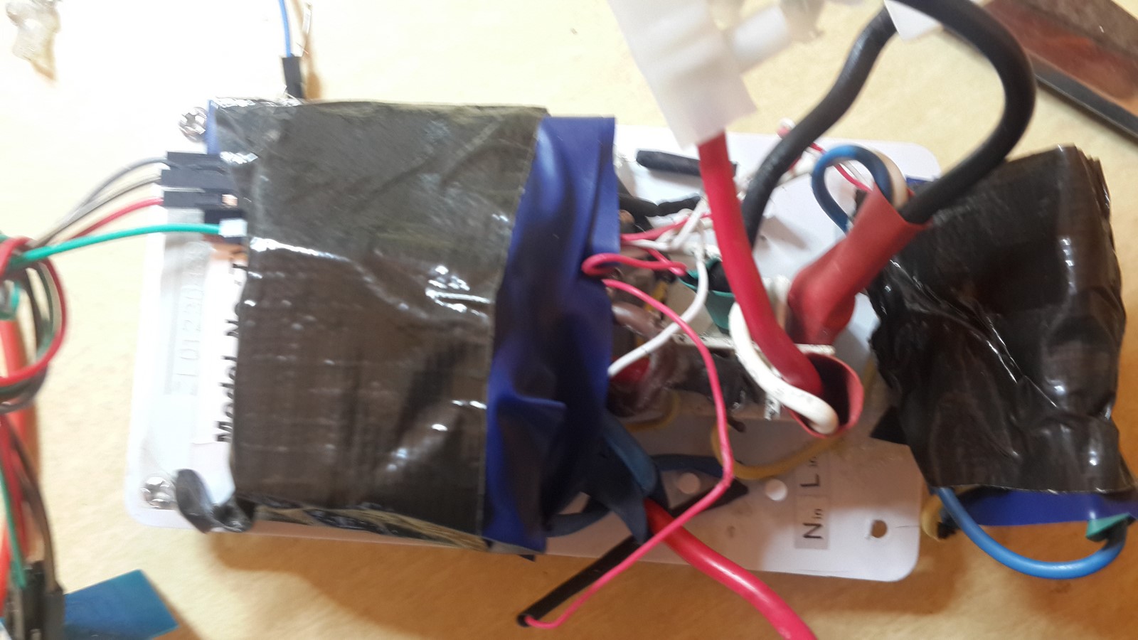
All the parts on the PCB eventually looks like in the picture below, I intentionly made this PCB long and thin so it can be fitted next to the relay module:
So now it is closing time. The most important part here is to isolate all exposed wires and make sure there are no moving parts. In my project, I had some high voltage exposed wires connected to the relay
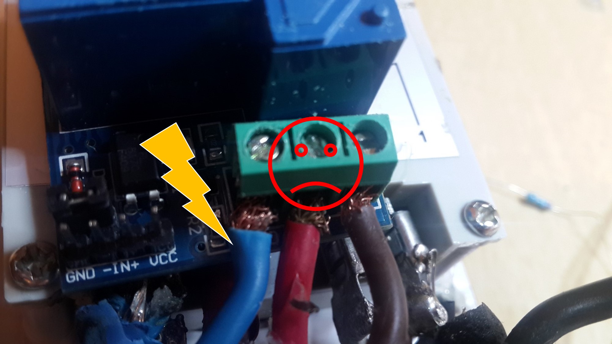
If your wires look like that - You gonna have a bad time!. If you are not authorized electrician I warmly advice to call one at this point, in order to verify your circuit. Some ways to handle with these wires, are to cut them, solder them, cover them with heat shrinks and put insulating tape (electric tape). One of the comments of this site advised to use ferrules connector and so I did.
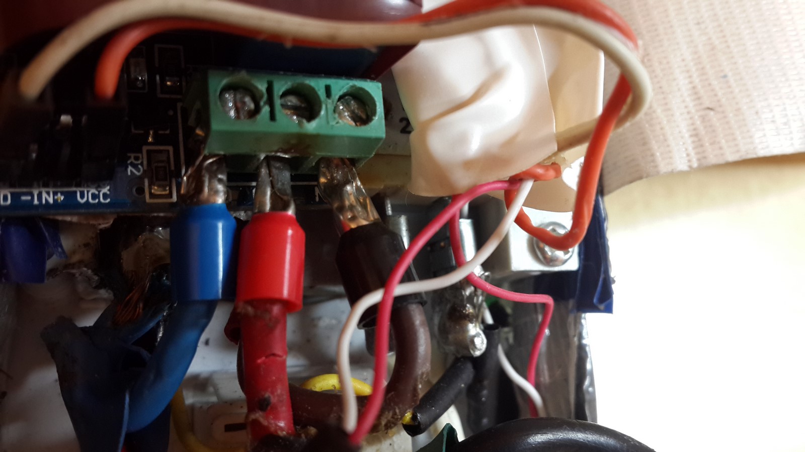
About insulating tape, one of its charachtaristics is that it isolates conductive wires. Finally, I decided to wrap everything with this tape to make sure no conductive parts are exposed.
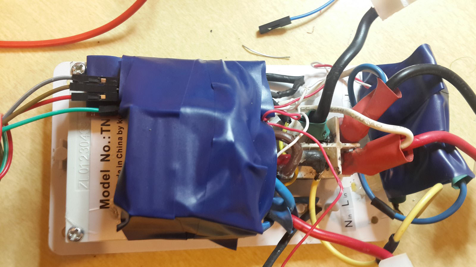
Next step, put some gaffer tape on everything so nothing will move (you can read here why gaffer tape is the best choice).
Finally, it is closing time. But unfortunately the plastic in the back is a bit lower than the water heater timer with the relay on top of it:
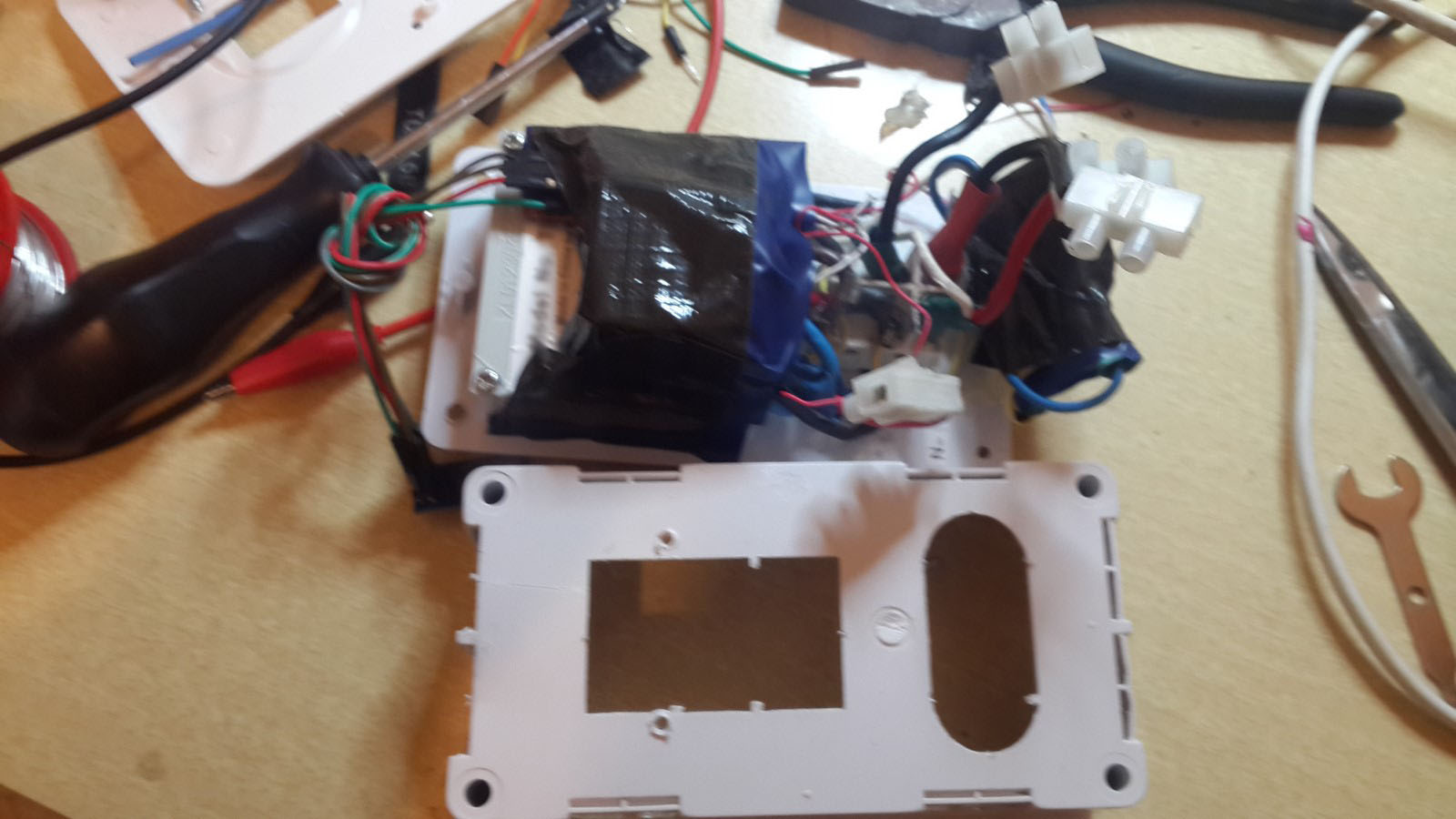
Two minutes working with a dremel will give you what you need
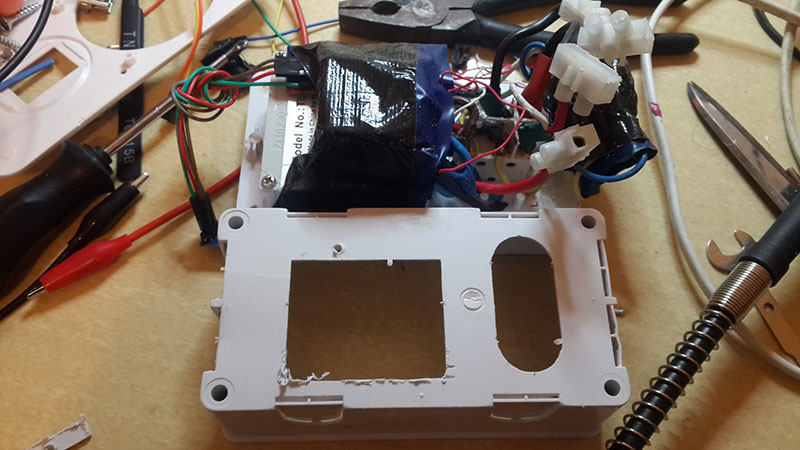
and the box can be closed
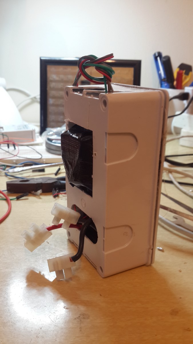
I intentionally left the ESP8266 outside the box since it is the only part that might need a version upgrade. I am not intending to finished this project by leaving a simple website with on and off buttons, there so much more to do from the software point of view - Schedules, GUI, Security, Email services, etc.
Now, unless you done it already, you can call an electrician to verify the box and connect it to the water heater - And you are DONE!
This project is actually a very generic project which can make almost any electrical device a smart house gadget, at a very low cost. Instead of water heater timer the same can be done with outlets, lamp switches, washing machines etc.
Happy Hacking!
Nicolas