This will be my first post in this blog, actually this will be my first post ever.
I started working with an arduino about two years ago and didn't really keep track of my projects, I used to build a project and then tear it down when needed some parts for a new project. So I decided to write a bit about some former projects before starting to write about current projects, most of them are not working today but at least me or you will be able to reconstruct them using this blog.
Today I will describe a project I built about a year ago, with a led strip (RGB), where the different colors in the strip will turn higher/lower by the different frequencies of a sound wave coming from a microphone. The red leds are controlled by the low frequencies (bass), the green by the mid frequencies and the blue by the high frequencies.
Here's a video to show you how it looks like (I think I made a few more adjustments after filming this):
What you need?
1 x Arduino (Uno,nano,mini-pro... Whatever you work best with)
4 x Resistors (The values can be adjustable)
1 x Ceramic capacitor
3 x TIP31C npn transistor
1 x Microphone sensor (EDIT: I was referred by the maker fabi that this link is to an audio sensor which outputs low values when there is sound. This is not the module I have used. I couldn't find mine on Ebay, but a similar one would be on this link )
1 x 5050 RGB led strip
and...
1 x Arduino code
Our basic circuit looks like this:
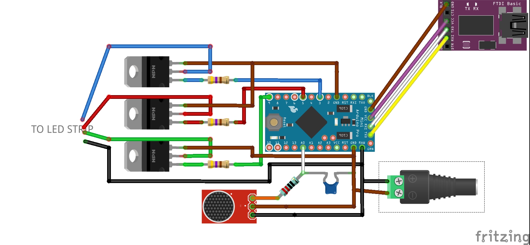
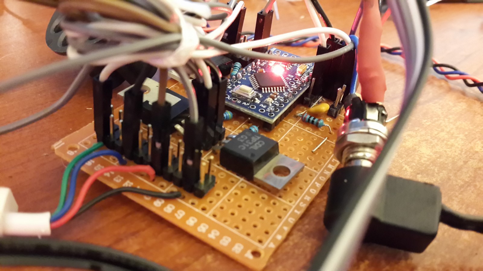
Arduino uno might be an easy option to choose to build this circuit, I however have used the arduino mini pro, since I wanted to make it as small as possible, put it on a PCB and take it with me to parties :P
Output
Let's start with the easy part, the output. In order to light few dozens of leds, you will need a lot of current, much more current than the arduino can give. That's why we will use our friendly awesome electronic part - the transistor. I chose to use the TIP31C because it can stand high currents, so basically you can connect many led strips together and it will still work. For those who never used a transistor - the idea is pretty simple, the transistor has three pins - Collector, base and emitter. We connect our circle through the collector to the emitter. The base is the "switch", connected to the arduino, and the arduino will control the switch by changing the pins state and allowing small amount of current to flow through it.

The output circle goes as follows - The black wire is connected from the strip to the power, usually 12V, and the red, green and blue wires which usually connected from the strip to the ground, are now connected to the collector pin, followed by the emitter pin which is connected to the ground. Each of the base pins of the transistors is then connected to one of the PWM pins of the arduino together with a resistor. At this point I would suggest using a variable resistor and then load the arduino one of the example codes which use PWM and checks the reaction. You will see that the PWM controls the entire strip, turning the leds brighter and darker, and the variable resistor does the same. After you play with it a bit you will find the right resistor to connect the base pin (I used 470 Ohm). Important note at this point - I've used the same power supply for the strip and the arduino, connecting it to the Vin/Raw pin. Most arduino can take 7-12V from this pin. If you use different power sources remember to connect both grounds!!!
Input
After we have convinced it is easy to control the strip we can connect the microphone. All modules usually have the same pins - "Vin","GND" and "OUT". My module was designed such that 12V were needed at "Vin" but sometimes it can be less so make sure you are not supplying more voltage than needed. The "GND" connection is obvious, and the "OUT" goes to one of the Analog Pins of the arduino.
The signals you would received from the microphone are voltage values which change according to the voice perceived. The human ear can hear sounds up to 20Khz, for this project signals up to 8Khz would be enough. There are not so many music instruments who has energy only at high frequencies. In order to filter the signal up to 8Khz we use an analog Low Pass Filter (LPF), using resistor and capacitor. As seen in the scheme, the "OUT" pin goes through the resistor, then to A0 pin, and the capacitor connects the resistor/A0 and the ground. It is recommended to use ceramic capacitor because it has a better frequency response.
To simplify, the values of the electronic parts can be determine by the next rule: Assuming we have resistor with value R and capacitor with value C. The frequency f where: $f = \frac{1}{2 \pi R C}$ is the cut-off frequency, meaning that lower frequencies will be almost not filtered at all and higher frequencies will be almost filtered completely. I chose capacitor of 100nF and resistor of 220 Ohm which gives cut-off frequency of around 7.23Khz.

CODE
Everything is connected and we can finally go to the code. My code can be found on github, however it was one of the first codes I ever wrote to an arduino so it is pretty messed up. I'll give some notes on the code but if you build this project and re-write the code I'll be happy to publish your code here instead and give you the credit.
Sampling
According to the Nyquist–Shannon sampling theorem, when sampling analog signals into digital signals we must use sampling of at least twice the maximum frequency of the signal. If we use lower sampling rate the sampled data will be distorted. In our case the sampling frequency should be at least 16Khz since the maximum frequency is 8Khz (Hey, don't you glad we used that LPF before? That was the main reason!).
Usually we will use the digitalRead() function in order to get the analog values from the A0 pin but this function can be rather slow and might not be fast enough for our sampling rate. Therefore, we can set the A2D to 8 bits instead of 10 bits, read the register directly, and by that save a lot of time. Here is the code that should be in the setup:
ADCSRA = 0;
ADCSRB = 0;
ADMUX |= (1 << REFS0); // set reference voltage
ADMUX |= (1 << ADLAR); // Using only 8 bits in ADCH register
ADCSRA |= (1 << ADPS2) | (1 << ADPS0); //set ADC clock with 32 prescaler- 16mHz/32=500kHz
ADCSRA |= (1 << ADATE); //enabble auto trigger
ADCSRA |= (1 << ADEN); //enable ADC
ADCSRA |= (1 << ADSC); //start ADC measurements
At this point, our hardware is working for us while the code is running, upadating the ADHC register with the digital voltage values at a very high rate. In order to sample the the values at 16KHz we can use interrupt using timers and get the needed values at the precise time. I however had some problem debugging the interrupt function back then, so I've used a more simple, less aqurate but good enough solution - getting enough samples using a loop and then continue the code:
int Buff=0;

  while (Buff<BUFFER/2) {
      Time2= micros();
      if (  Time2 - Time1 >= 56) {
          Time2= micros();
          mic_NoFilt[Buff] = ADCH;//analogRead(micPin);
          timeDT = Time2 - Time1;
          Time1 = micros();
          Buff++;
      }

  }
Reading sample every 56 microseconds will give us sampling rate of $\frac{1}{56*10^{-6}} = 17857Hz$, a bit more than we need. I chose a buffer of 20 samples. Bigger buffer might give better results afterwards but will take more computation time and therefore would cause a delay between the music and the RGB lights.
Filtering
When describing the input we've talked about the analog LPF, now we going to use digital filters in order to get the values we want for each of the RGB leds. I should state here that this whole part can be done using a bit more complex analog circuit and then we wouldn't have to use the arduino at all, but it will be less fun :)
In order to filter the signal we will use a Finite Impulse Response (FIR) filter. The idea is to multiply all the samples with a set of weights and then sum. Assume W are the wights and S are the samples, the output filter V would be:
$V = \sum_{i}{Wi \cdot Si}$
For example, if we use the same normalized weights for all samples we will get a filter which passes only the DC value (i.e frequency=0). I'll get to this example at the end of the post.
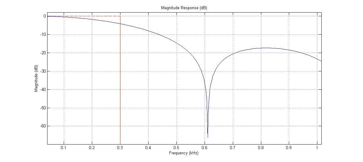
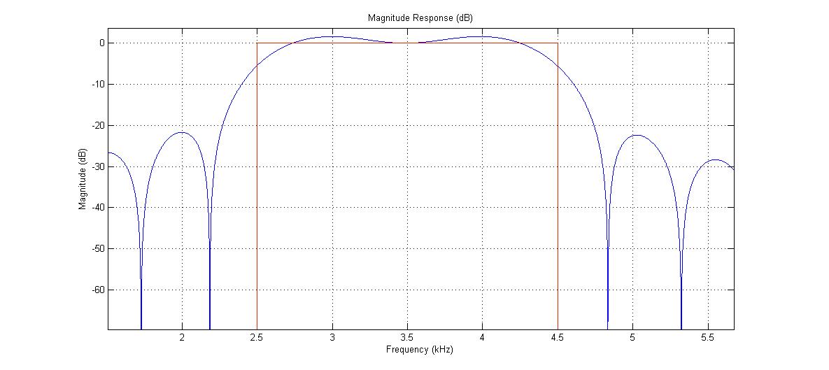
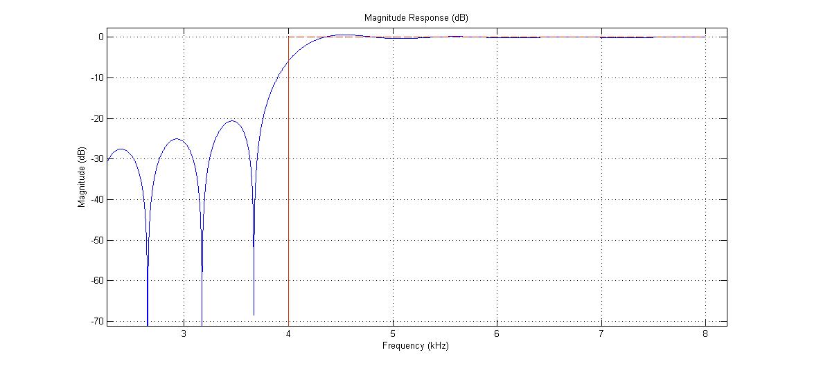
I will not get into the whole FIR theorem but it is easy to get the weights using the signal processing toolbox on Matlab or just use the weights in my arduino code. With this code I created 3 filters:
- Low Pass Filter with cut-off at 300 Hz.
- Band Pass Filter with cut-offs at 2500 to 4500 Hz (filter everything lower or higher than this values).
- High Pass Filter with cut-off at 4000 Hz (filter everything lower than 4Khz).
This is a visualization of how the filters look like:
The weights will be stored in the code and all we left to do now is filter the selected samples with the selected weights. The FIR code is easy to implement but a bit hard to debug in case of errors, so I chose the safe path and used this code which consist of FIR function, which has already examined by another user. After filtering the samples we will get a certain value, which can be used for the PWM to control the RGB lights. For example, You will note that the values of the first filter (LPF) will be bright only when there are bass sounds and almost zero otherwise.
Some Practical Issues
Theory is nice but in practice not everything is accurate, even if it is accurate, the results sometimes will not be satisfying. Here are some issues from my experience:
Filter DC values - Only the LPF should have a DC value as part of the filter result, but practically all filters have it. In order to filter these values just take the first 5 seconds of the code measuring them, assuming no music is played yet. After you use each filter save its value and at the end of the 5 second find the average value - this will be your DC value. When the main code starts you can subtract this value every time after filtering. In my code the function
CalcDC()does these calculations.Normalize the filters output - It could be that one FIR filter will give you values of 0 to 255 while other filter would give values of 0-40. If you want the RGB lights to turn on at relatively equally brightness you should normalize your values. In my code, while calculate the RGB brightness values using the function
micVal2Brightness()I also save the min and max values and normalize the brightness to get values of 0 to 255.SetFade()- The music was loud and then stopped? Write a fade function so the lights will not instantly turned off.Solder everything on a PCB - make it small as possible, take it out of your pocket in a party and amaze people! :D
If you still reading this I hope you enjoyed this post. I find signal processing fascinating and not so hard to understand. I think because there a lot of theory behind it people are afraid to get into it. If you build this project post here when you done or during the process if you have any questions.
AA