My niece had a birthday this month, she became 13 years old. I'm really bad at choosing a birthday present for a 13 years old girl so I had two choices: Ask my girlfriend to help me buy a present or build her something. I decided to go with the easy way - Build something. It actually started from an experimental play with leds as pixels and eventually become this:
What did you just see? The leds have a mirror behind them and a reflective glass in front of them - giving them a 3D-style look. The moving patterns are Hebrew letters, meaning "Ruth" (רות), which is my niece's name.
This is actually a very simple project, where the software might be more interesting than the hardware. Lets start with the parts you'll need:
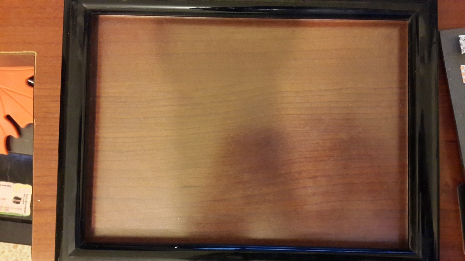
- Picture Frame - Mine was 18cm x 13cm
- WS2812 led strip (80 leds, from 60leds/m strip)
- A mirror and a reflective glass, same size as the frame
- Arduino Pro Mini, 5V
- 3 x Resistors (330Ohm, 15KOhm, 220KOhm)
- 220uF Capacitor
- A Button
- 5V Power Bank
- Wires and Tabbing Wire (you can use only wires but it can help)
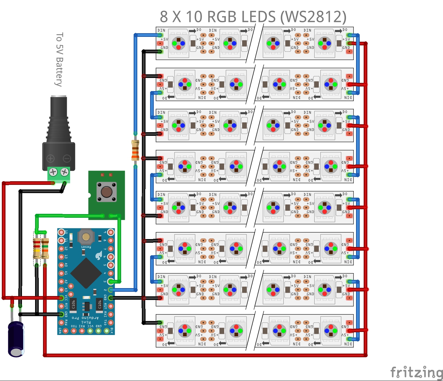
The electronic sketch is pretty simple as well:
Phase 1 - Led Picture
It all started when I found a picture frame in my house, with no picture inside, I think I once had an idea to make it into a solar panel.
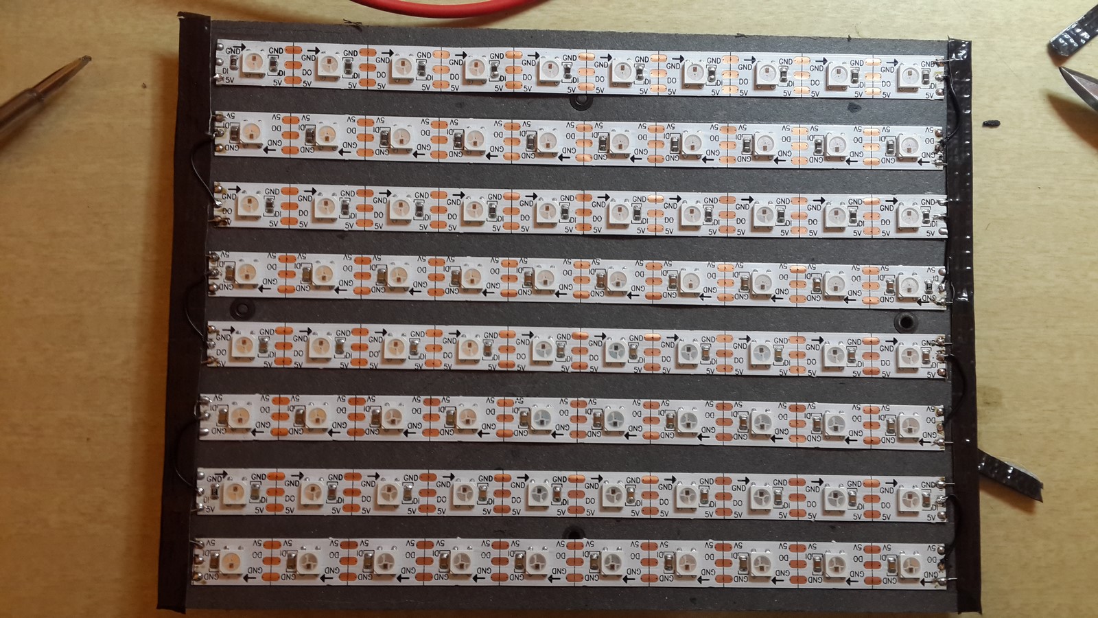
I decided to make it into a led picture, had a vision in my head that I could put it on the wall or something. So I've started by cutting some leds from my WS2812 led strip and paste them on the cardboard behind the frame. I paste them such that every row is opposite to the one above it since eventually I'm going to connect it as one long strip.
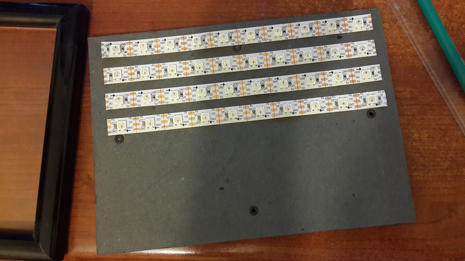
Watch out of any metal parts on the cardboard, they can short some of the leds if the connections touch them. When you're done, put two tabbing wires on both sides, one is soldered to all 5V connections and the other one to all ground connections.
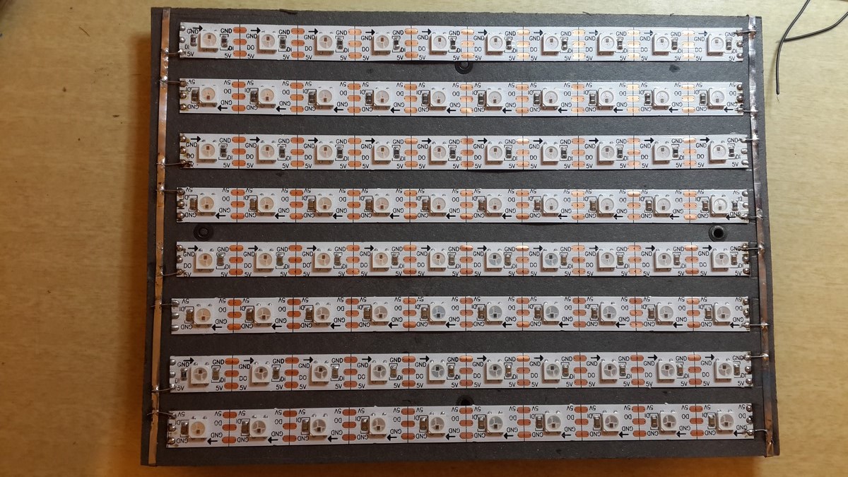
Next, solder all the "in" and "out" connections. Since we paste it such that every other line is upside down it is pretty easy to solder wires from every "out" connection to the next "in" connection below it. Last, cover everything with gaffer tape
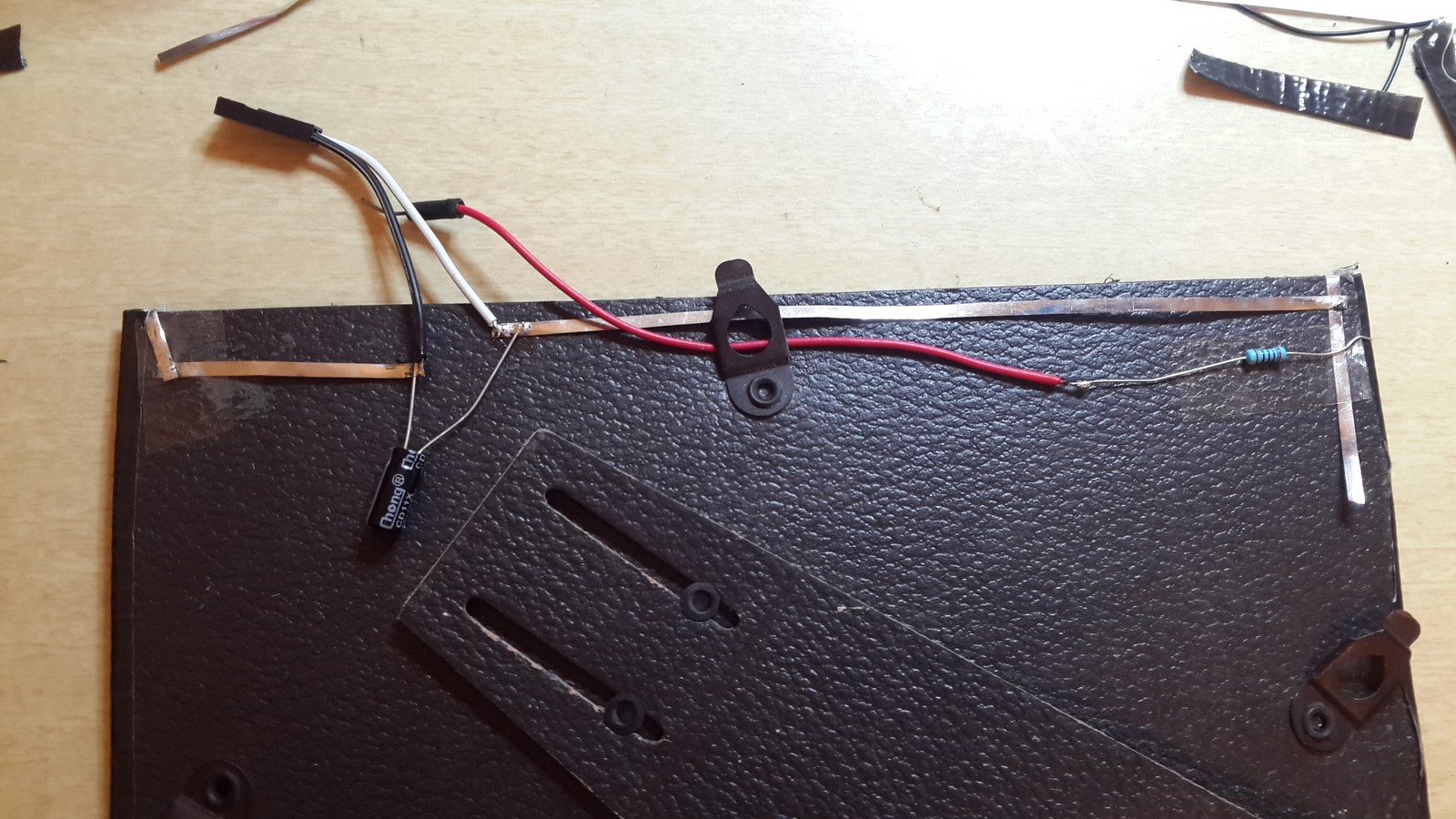
Turn it around and connect the wires from behind, together with a resistor and capacitor. I quote from another post of mine, where the "In" was connected to pin 4:
The WS2812 led strip is connected to 5V, GND and pin 4. In order to protect the leds and the WS2811 chip, a 330Ohm resistor is connected before pin 4 and a 220uF capacitor is connected between the VCC and the GND.
At this point, we can connect the leds to an external power source and arduino UNO (or any development kit) and start coding. If you want, you can go straight to solder everything on a PCB using an arduino pro mini. The disadvantage is that uploading programs to this arduino could be rather tiring when you do it a lot.
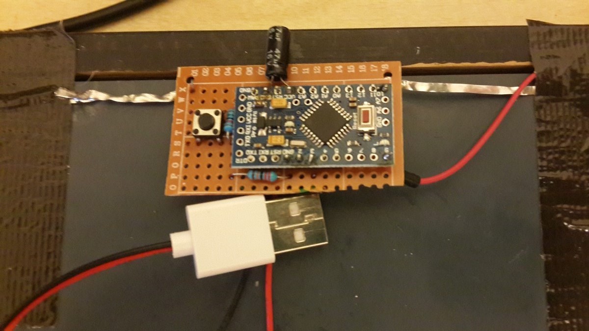
I added also a button since I felt like I will want to control the animation sequence manually at some point. The button is connected to INT1 (pin 3), through a pull-up circuit with two resistors. Why the two resistors? So at pin 3 input there will always be either HIGH or LOW values.
Phase 2 - Software
First, get the Adafruit NeoPixel library and add it to your project, this will allow you to easily control a WS2812 led strip. As for now, we have 8X10 pixels picture, but in real life it is only one long strip, moving in "zigzag" shape from top to bottom. So the first function I wrote was a function to control the picture using 2D parameters (X,Y) instead a one value control:
void colorPixel2D(char x, char y, uint32_t c, boolean isShow, int dly)
{
  if (y%2) {
    strip.setPixelColor(((int)y+1)*(COL)- (int)x-1, c);
  }
  else{
    strip.setPixelColor((int)y*COL + (int)x, c);
  }
  if (isShow) {
    strip.show();
    delay(dly);
  }
}
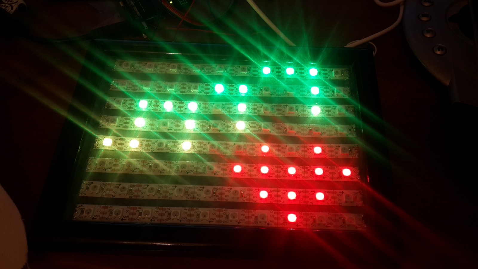
This function receives X,Y value and RGB color and sets the selected pixel to the selected color by checking if the row number is odd or even. My first try was to check if I could light the strip vertically and not in "zigzag".
GOOD!!
Next, a class is defined, with functions to control any defined pattern. The class consists of memory allocation, fading, moving, changing color and more. The shapes are defined very simply as X,Y values, for example a heart shape will be written as:
#define HEART_PATTERN_X 1,3,0,1,2,3,4,1,2,3,2
#define HEART_PATTERN_Y 0,0,1,1,1,1,1,2,2,2,3
#define HEART_PATTERN_SIZE 11
From here it was much easier to start writing a sequence which will show letters and patterns, move them, change their color and more.
Finally, I got some help from Notamacuser, arranging the code much better, and it can be found on this github link. It consists .h files for the patterns and the functions, and .ino file as the main function. It is very easy to add more patterns and letters to the code - You can try it yourself.
The main function code consists of an animation as you can see in the short video at the beginning of the post, and the button is connected to an interrupt which changes the sequence manually.
Phase 3 - Going 3D
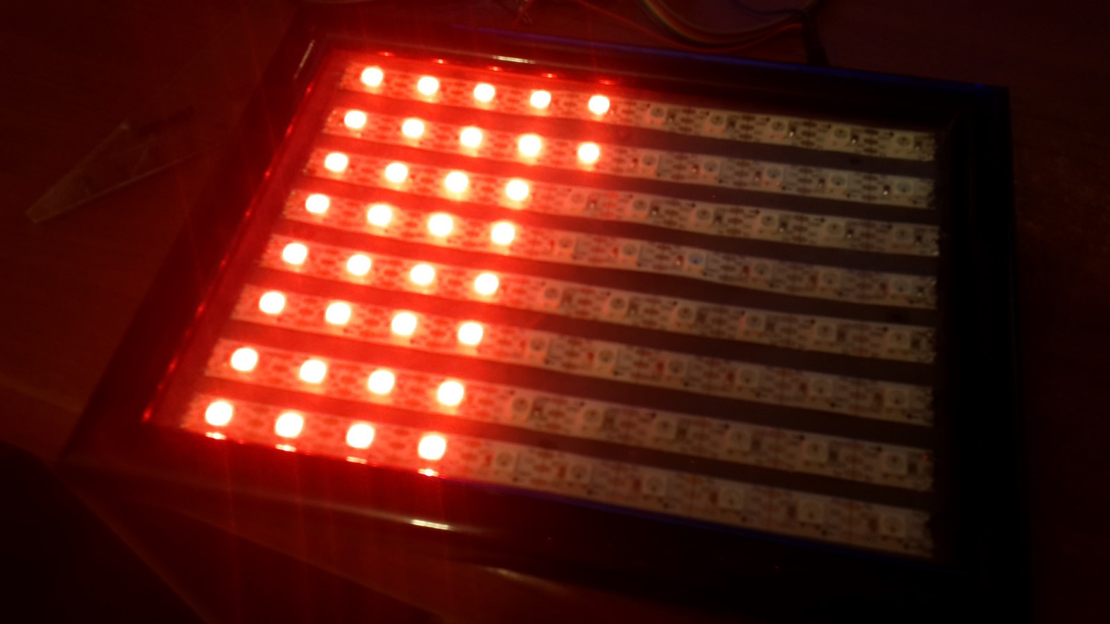
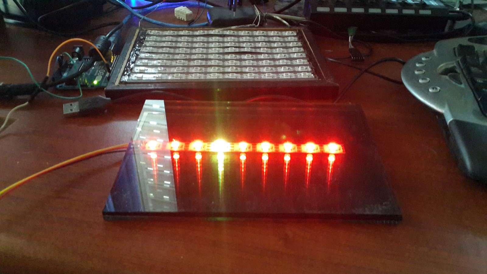
At this point I read about this nice visual trick of putting a light source between a mirror and a reflective glass. Not surprising, the reflective glass reflects high amounts of the light back to the mirror and vice verse - creating some kind of 3D infinity illusion. I immediately went to a small glass-cutting factory and got a mirror and reflective glass with the same size of the frame. Their size was so small (18cm x 13cm) that the nice guy at the factory cut it and gave it for free. This is how the effect looks like with a single strip:
It was a bit of hard work, but I managed to take out all the led strips I paste on the cardboard, and paste them on the mirror. In front of the leds I put the reflective glass and closed the frame. The new led picture looked like that:
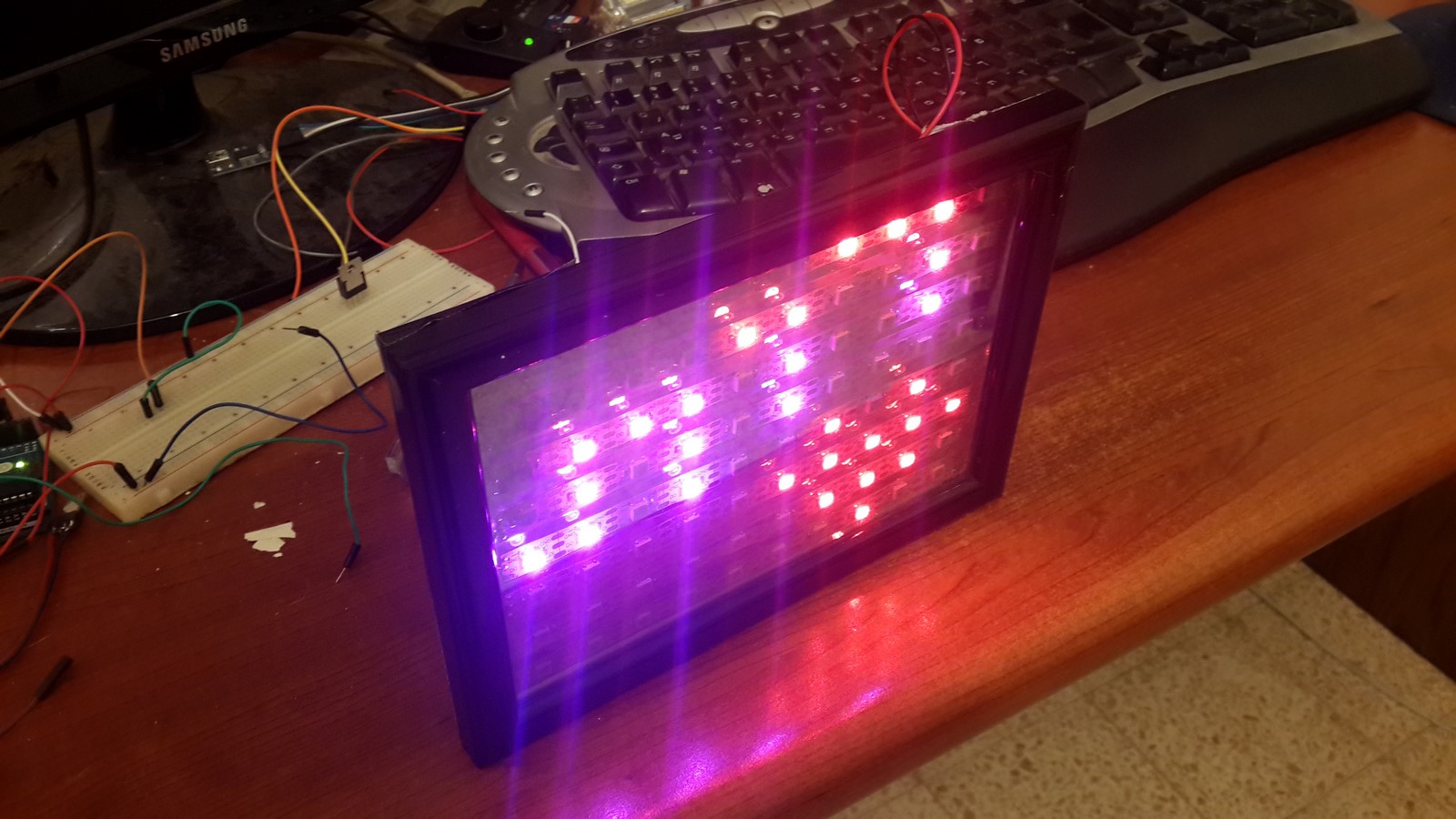
Not really infinity-style, because there were too much leds, but still cool 3D-style.
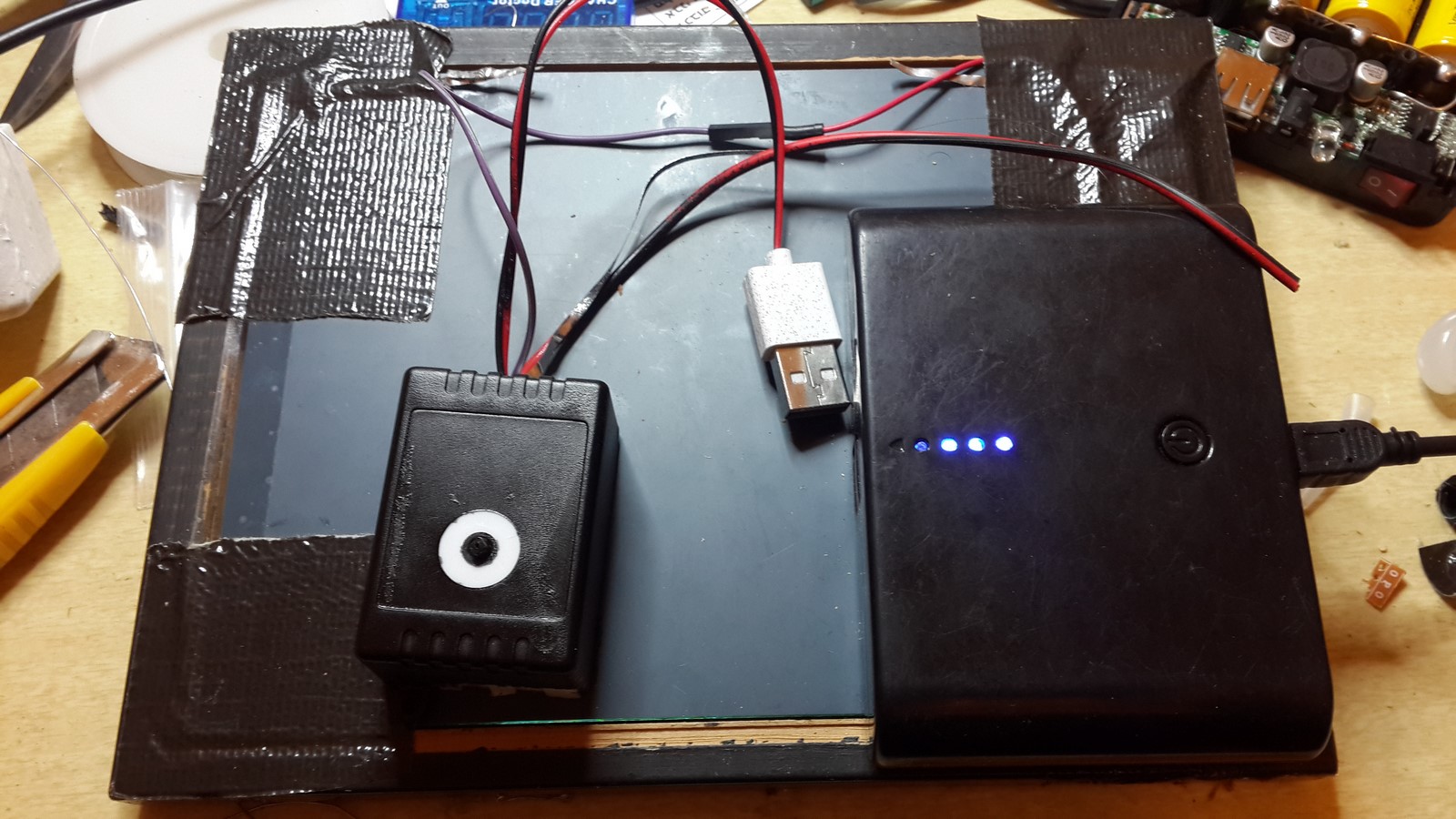
Phase 4 - Energy and Electronics
The led picture was ready at this point, but there was still the matter of which power source to use and final actions to make the picture robust and stable.
Measuring the current, I found out the leds picture takes around an average of 400-500mA, depends on the animation. That's quite a lot of current for a battery powered project and I had to choose which battery to use. My first decision, which is pretty obvious, was to use a rechargeable battery, Li-ion to be precise. These are very common, can produce a lot of energy compared to their size, and usually comes packed with electronic circuit which already produces 5V and also easy to charge - That's because most people use them to charge their phones (a.k.a battery bank). I had two kinds of these battery banks at my house, both where ordered from Ebay, one was stated as 5000mAh and one was stated as 12000mAh. To understand more what "mAh" means you can read my post about batteries and phone chargers. Just like many other items on Ebay, both of these batteries didn't supply the energy they were suppose to. The first battery bank lasted for about two hours, meaning it has capacity of around 1000mAh, and the second lasted for nine hours, meaning it has the capacity of around 4500mAh. I decided nine hours will be enough for this project and went with the second choice. Unfortunately the batteries were very heavy and my first idea to hang this picture on the wall didn't seem so practical anymore. So I decided to go with building a stand to the picture, just like those picture of your family which you put next to the computer in your office :)
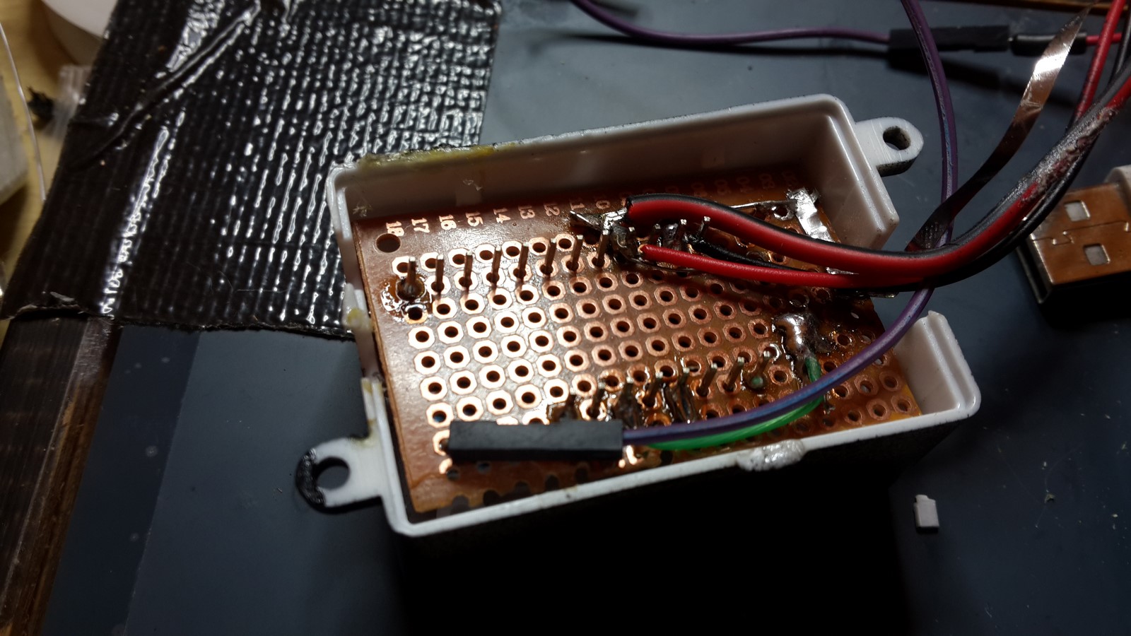
Moving on, I wanted to make the PCB and the arduino hidden but still have the ability to press the button. I found this small plastic exactly the size of the arduino which originally belonged to a Led strip controller. I put everything inside:
Also paint it black, except a circle around the button:
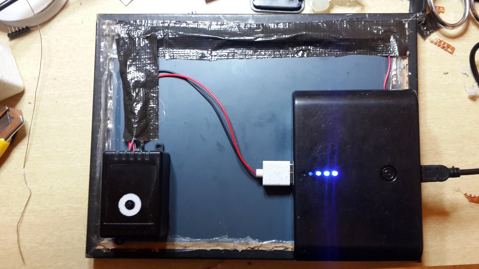
Next, it was time to arrange everything at the back of the picture frame. I started by gluing the small cracks between the mirror and the wood, using hot glue.
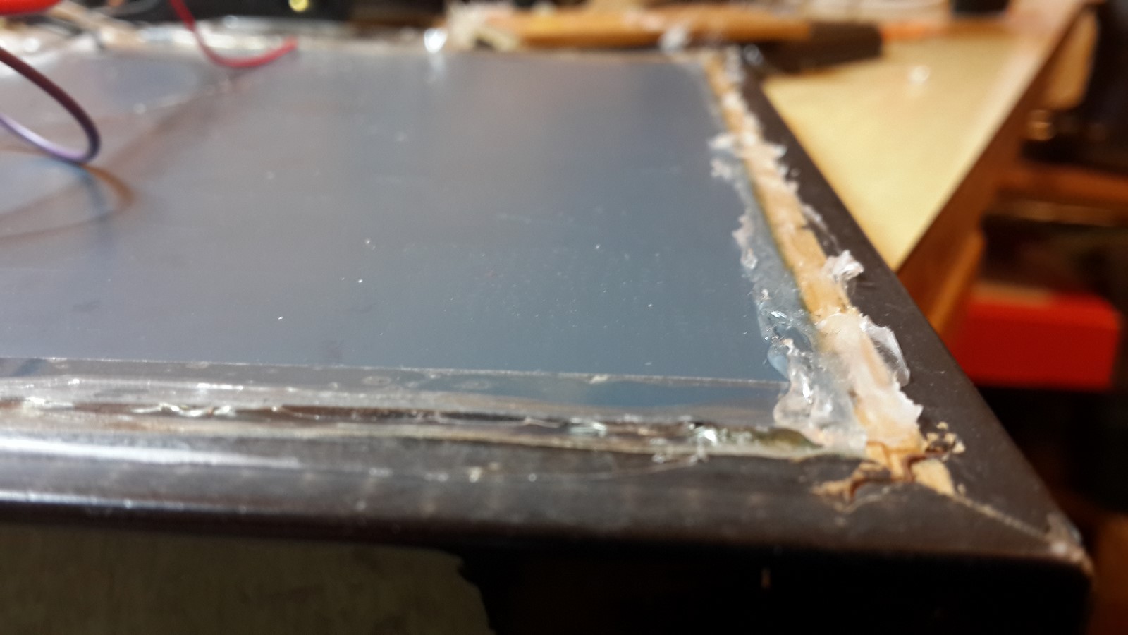
Then I taped all the wires so they will be hidden, and glued everything to the back of the mirror:
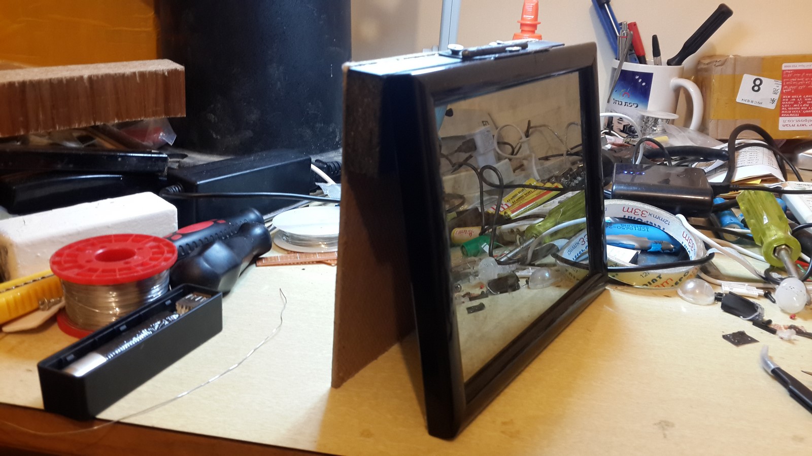
Phase 5 - The Stand
The last part of this project was to find a way to make the picture frame standing. I made it using a piece of particleboard glued to a piece of thin flat wood, both were sawed with a jigsaw to fit the size of the frame, and were painted in black to fit the overall spirit.
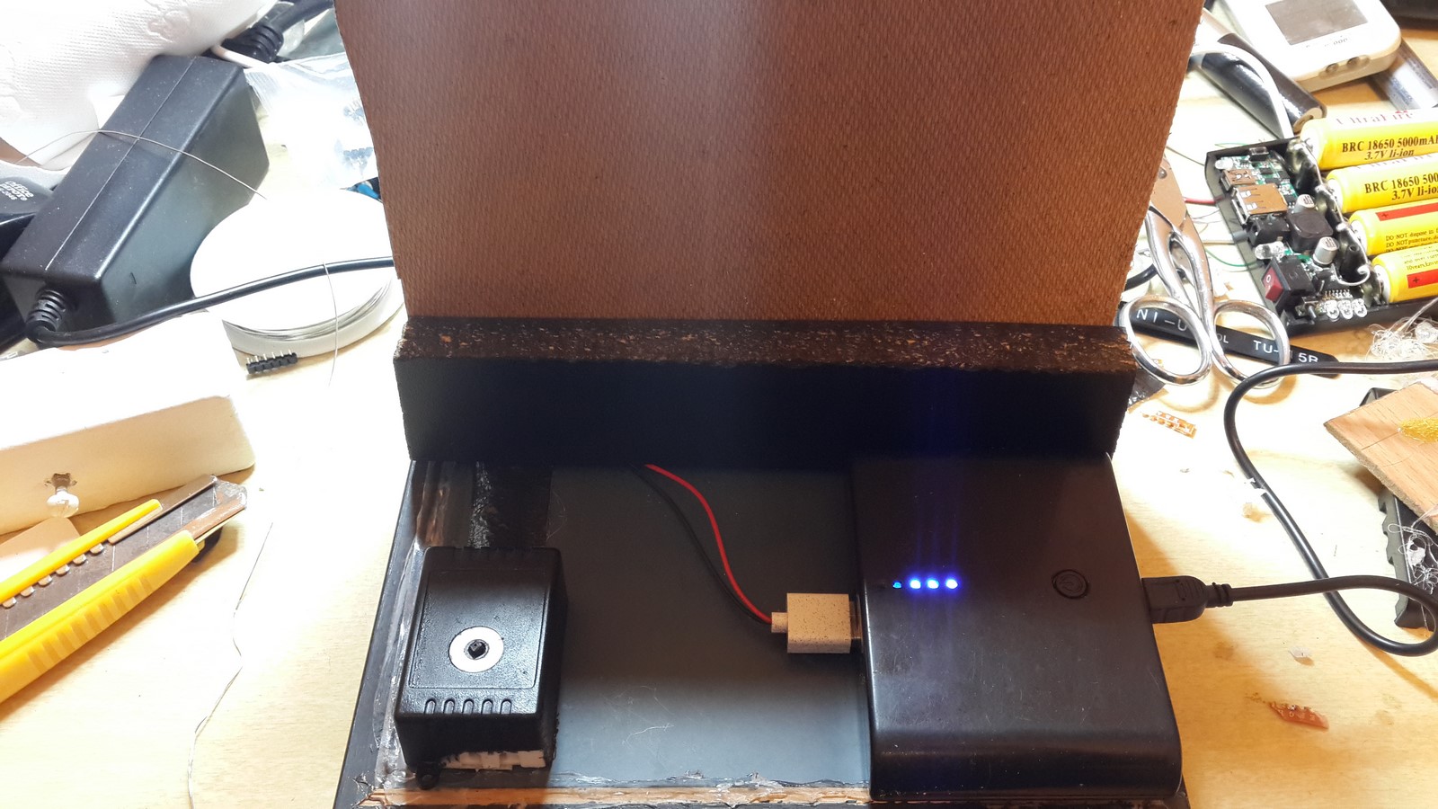
To connect the wood to the frame I've used a hinge. This is actually the only part I'm not so proud of because it turned out ugly in my opinion. But I didn't have any idea how to fix it so went with it:
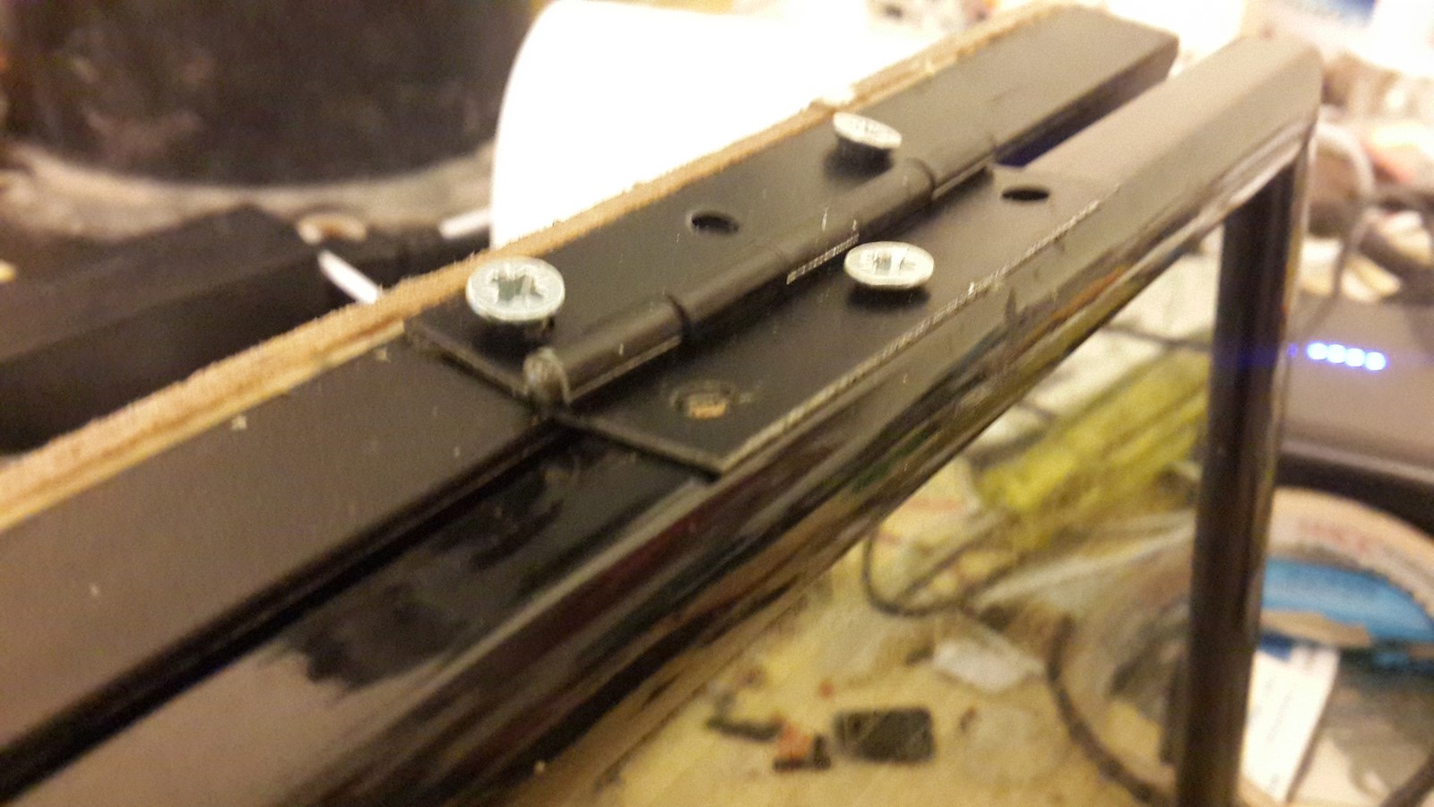
I was afraid to screw more screws to the frame so I also glued the hinge to the frame using E6000. And that's it! The 3D magical led picture is ready!
Final tip: I found out the wood and frame were slipping when the stand is opened too much so I put a bit of hot glue at the bottom of the frame and the wood and it solved the problem
Final Thoughts
I really enjoyed making this project - I found myself using a lot of junk from my house but also trying to use some new equipment and tools. The software was also a good practice, even though it was very short - The idea was to write the software in such a manner so people could update and add their code to my code, and the next people will have a better code to use. I hope you'll do that if you are planning to build this project.
P.S
Today I finally gave the present to my niece and she was really excited with that!! Her older sister also had a birthday this week and me and my girlfriend decided to buy her a necklace - No worries she was happy as well :P
AA