My Web Cam Can't See
We've all been there. We install a web cam, march off to our screen to check what it sees, then come back to make adjustments.
Of course, we're never really satisfied; there's always something more interesting happening out of frame. When you're viewing remotely, there's not much you can do.
Vacation Security
When I go on vacation, I usually set up a Raspberry Pi or two with cams to keep an eye on things. (For the truly keen-eyed reader, did you notice I'm still using an original Pi B with only two USB ports?) Using MotionPie it's easy to set up a remote camera that will:
- Be accessible through the internet
- Detect movement and send you an email with recorded photos
- Save still shots and movies of movement detected
The problem is, you need to set up your camera before you go, and once it's in place, you can't move its field of view.
$2 solution
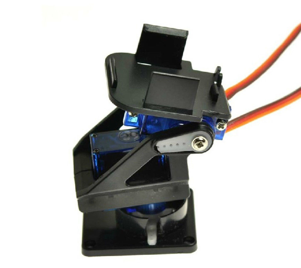
That's why I bought this. For just a couple of bucks you can pick up a Pan & Tilt platform that lets you move your camera remotely. Of course, you need a couple of servos too, but they don't cost much either.
MotionPie Doesn't Do Servos
MotionPie is a disk image, and from what I can see, when it's running on the Raspberry Pi, the RasPi's GPIO pins aren't available to control servos. (I'm probably wrong about this, but being a hobbyist with no programming skills, I'm always looking for the easy way).
(Editor's note: since writing this post more than a year ago, I've since written a more detailed post showing how to use a Raspberry Pi to control a camera AND servos. It can be viewed at this link.)
My Solution
So how do I move my camera around while running MotionPie, if I can't use the RasPi's GPIO pins?
My solution was a simple ESP8266 01, controlled by blynk.
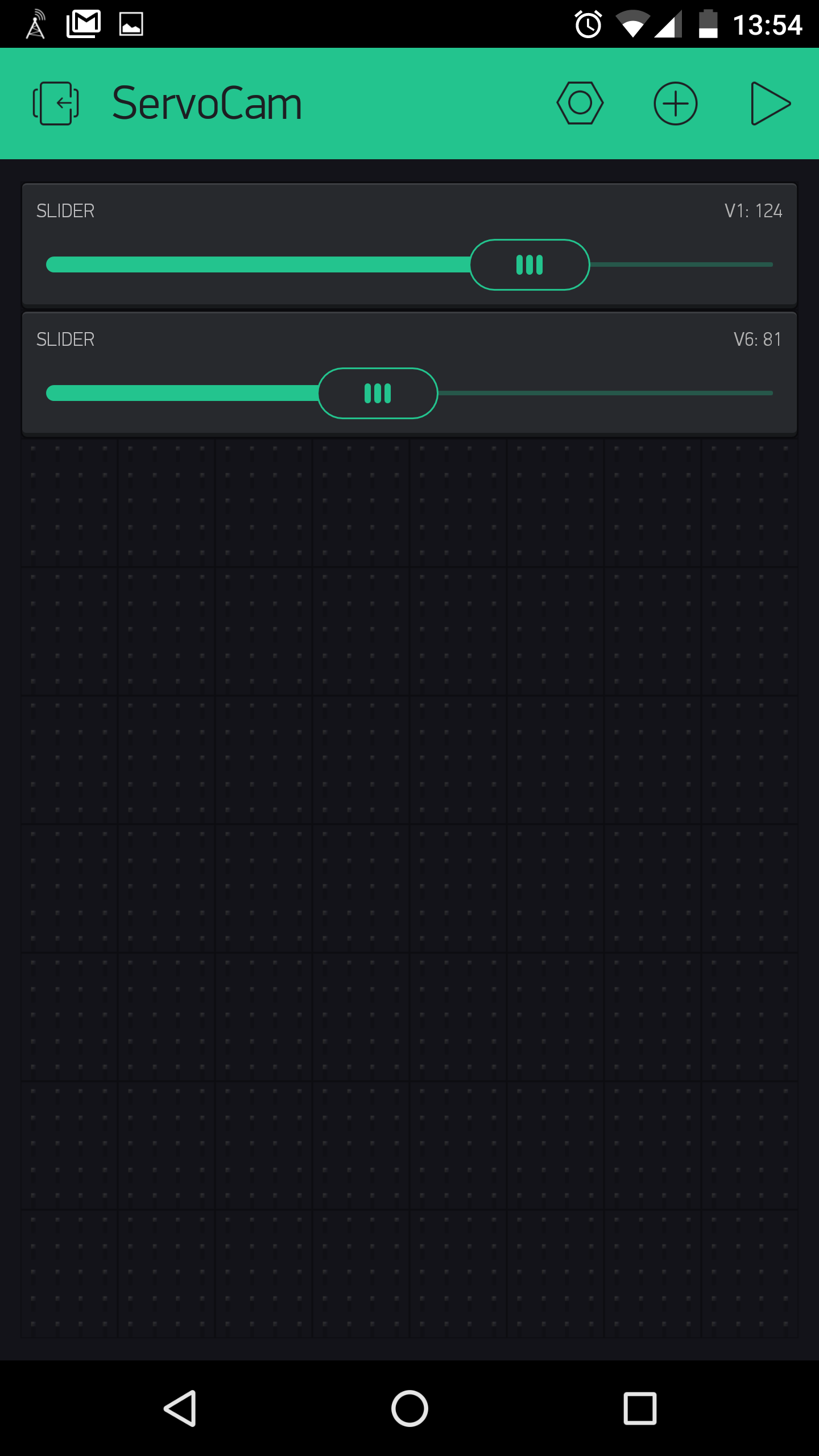
To control the servos, I only needed two signals - one for each servo. The ESP 01 was perfect for this. Using GPIOs 0 and 2, and Blynk's sliders, I can control my camera's Pan & Tilt from anywhere.
Parts
- ESP8266 01
- Blynk account
- Cell phone!!!!
- Two servos
- Pan and Tilt platform
- Two 470 uF capacitors (used to dampen interference on the servos)
- 5v power source
- LM1117 voltage regulator
The voltage regulator is used because the servos need 5v to operate but the ESP works on 3.3v. The 5v feeds the servos directly, and goes through the LM1117 to the ESP.
The Sketch
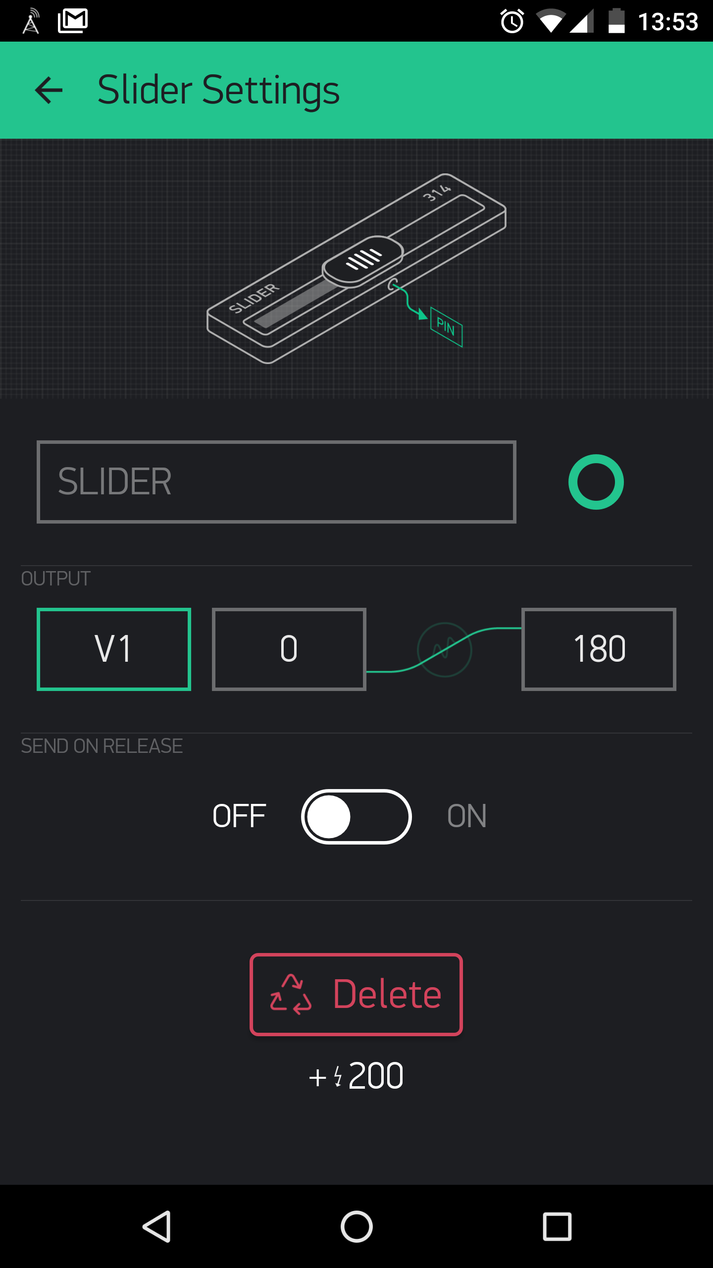
This is the sketch I used. Two things to note: The servo physical pins are attached to GPIO 0 and 2, but blynk uses virtual pins to control the servo. I used V1 and V6. (When I tried V1 and V2, I got lots of interference. I'm sure renumbering them doesn't explain the reduced noise, but if it works, it works!)
The second thing to note is that the scale for each servo should be set to 180 (rather than 255) as the servo only travels 180 degrees.
#define BLYNK_PRINT Serial
#include <SPI.h>
#include <BlynkSimpleEsp8266.h>
#include <Servo.h>
#include <ESP8266WiFi.h>


// You should get Auth Token in the Blynk App.
// Go to the Project Settings (nut icon).

char auth[] = "xxxxxxxxxxxxxxxxxxxxxxx";

Servo servo;
Servo servo1;

void setup()
{
  Serial.begin(9600);
  Blynk.begin(auth, "ssid", "password");
  servo.attach(0);
  servo1.attach(2);
}
BLYNK_WRITE(V1)
{
  servo.write(param.asInt());
}
BLYNK_WRITE(V6)
{
  servo1.write(param.asInt());
}
void loop()
{
  Blynk.run();
}
This is what blynk looks like: