Update July 2020 - if you're interested in creating a mailbox notifier that'll work on regular AA batteries literally for years, take a look at my latest post here.
This blog was originally posted in June 2016. Feel free to read on, but there’s a substantial update (Oct 2017) that I wrote following many recent developments. I've tagged it to the foot of the post.
I'd also recommend reading the comments that follow the post.
Original Post starts here....
As a regular reader of this blog I contacted its moderators to present my problem.
I live in the upper two floors of a three-story building. Below me is another family, and below them, is our communal carport - surrounded on three sides by concrete.
My mailbox is attached to the wall of the carport, accessible at ground level to the passing mailman.
My problem is that I need to descend about 40 steps to get to the mailbox and like so many others obsessed with cheap Chinese electronics, this means constantly running up and down to see if my latest acquisitions have arrived.

Mailbox Alert
The obvious answer is a mailbox alert system.
I’m a tinkerer in electronics with no formal training. I knew the creation of a mailbox alert wasn’t complicated - and from reading this blog I knew the answer lay somewhere in the ESP.
Fortunately, Amir and I live in the same city, so I invited him over to view the problem.
Assessing the scenario, he nodded wisely. “It shouldn’t be complicated,” he confirmed. Such words coming from an expert were very encouraging - but didn’t take me far towards my goal. He assured me he’d be on hand if I got stuck.
I spent the next few weeks playing with the ESP. I learned to flash it with the Arduino IDE and make it blink an LED. I also toyed with IoT, but lacking technical know how, I made very slow progress.
Blynk
One day, while fiddling, I read about Blynk. Apparently, smart programmers had done the work for me, and all I needed was to:
- download the blynk libraries to the Arduino IDE
- put the app on my phone
- set my board
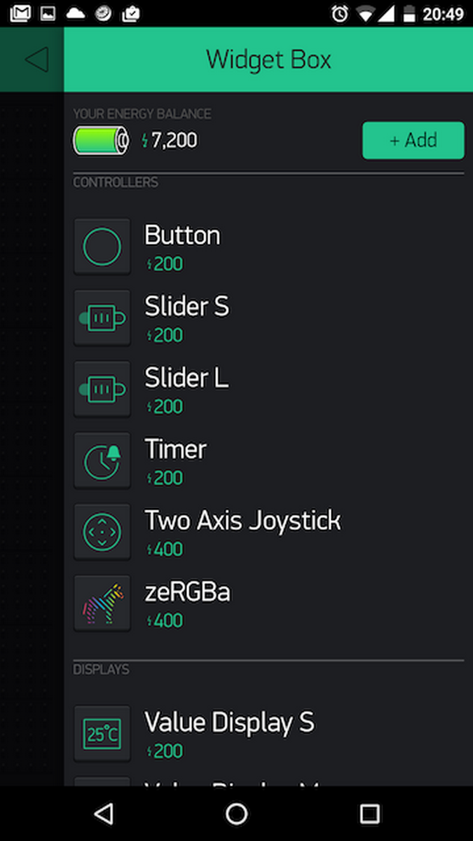
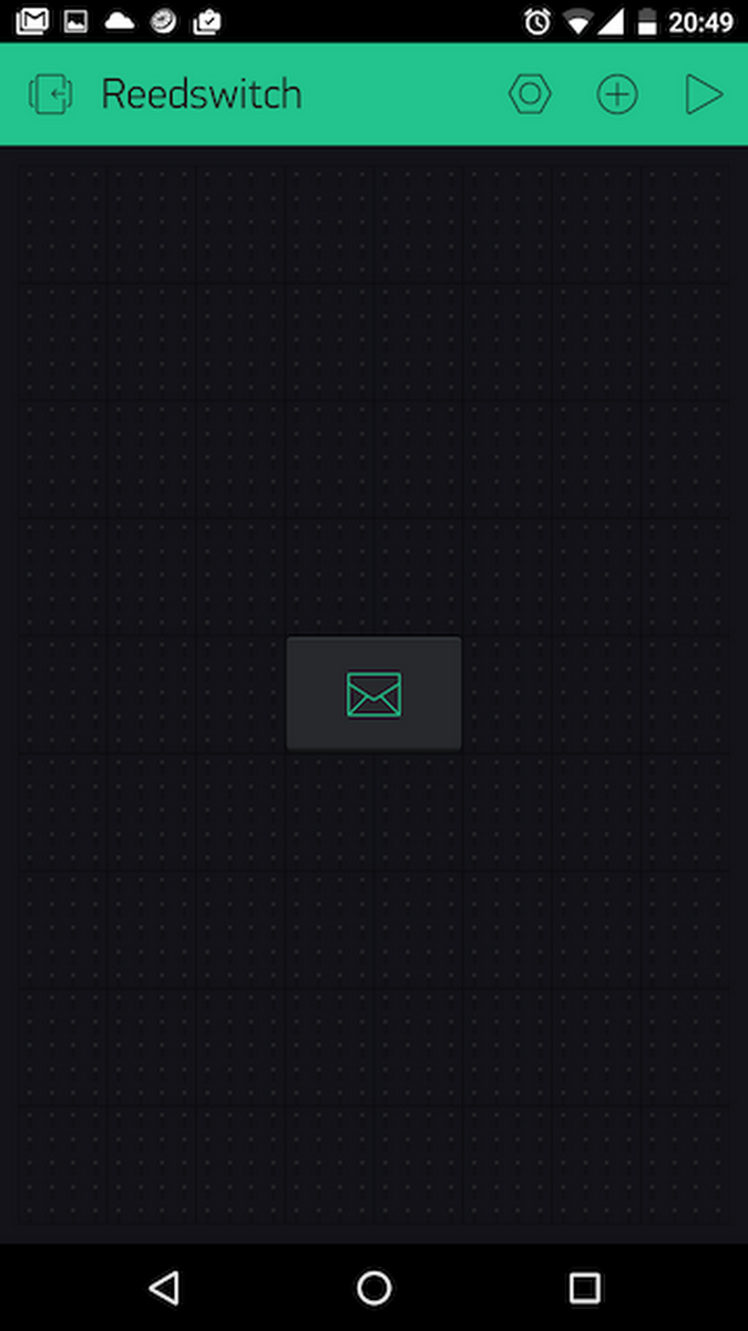
- add a few buttons
- get an authentication key from the blynk app
- flash the ESP
Even for the non-professional it was very easy, and by the evening’s end, I was controlling an ESP-connected LED from my phone.
I could see that creating my mailbox alert was at last in sight!
The Parts
My mailbox has a metal flap. The postman opens it, drops the mail inside and walks away.
I thought of using a motion sensor, and even a light sensor, but neither seemed as sensible as a simple magnetic switch (reed switch) that would sense when the flap moved. Such switches are very common in burglar alarms, usually attached to a door or window. I ordered a couple through ebay and ran up and down 40 steps a day as I waited for them to arrive.
Reed switches are mechanical. They are basically two fine contacts contained in a glass capsule. When a magnet approaches, the reeds move into contact, completing the circuit. A “normally open” (NO) switch has the contacts apart when there is no magnet around. A “normally closed” (NC) switch is closed until the magnet is there. I bought NOs.
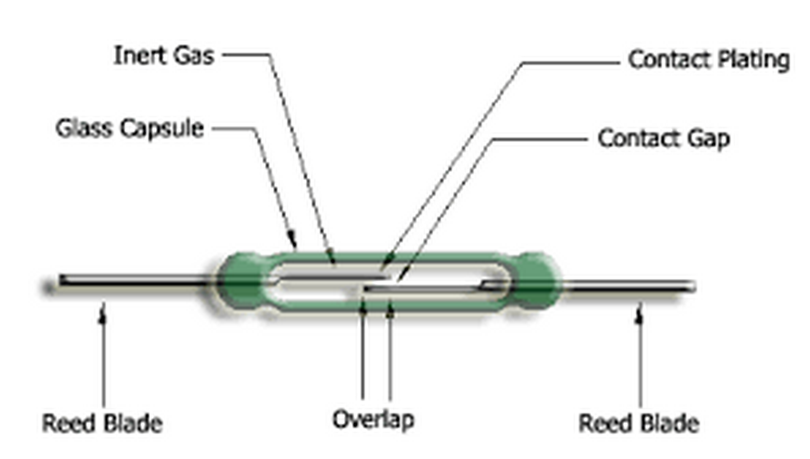
When buying them I thought I wanted the switch to close to activate the circuit, so naturally I want it to start in an open position - i.e. normally open (NO). What I didn’t realise was that when my flap is down, the magnet is next to the reed - so closing the circuit. When the magnet moves, it’s actually opening the switch, not closing it - the opposite of what I’d intended. For the electronics junkie that’s not a problem, but for someone with little experience, it’s just another hurdle to overcome.
There was an added problem. Often, when the mailman makes his delivery, the flap doesn’t fully fall, but gets caught mid air by a large envelope or magazine. That means the reed switch doesn’t close again. Another obstacle to tackle.
The First Working Prototype
A couple of evenings later I had my first prototype built. I used the ESP 01, attaching the reed switch to GPIO 02. The only other component was a 10k pulldown resistor. My very simple Sketch was taken from the ESP8266 Standalone example in the Arduino (ESP) Blynk library.
#include <ESP8266WiFi.h>
#include <BlynkSimpleEsp8266.h>
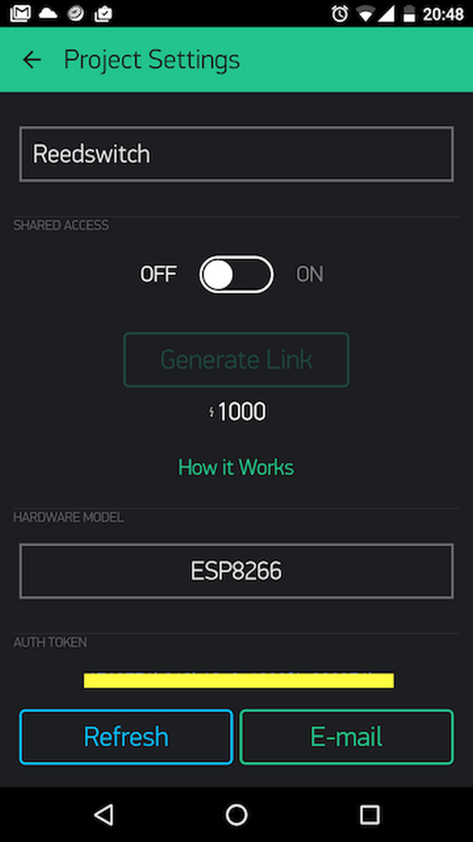
// You should get Auth Token in the Blynk App.
// Go to the Project Settings (nut icon).
char auth[] = "xxxxxxxxxxxxxxxxxxxxxxx";
void setup()
{
Serial.begin(9600);
Blynk.begin(auth, "ssid", "password"); // this connects the ESP to your wifi
}
void loop()
{
Blynk.run();
int isReedSwitchOpen = !digitalRead(02);
if(isReedSwitchOpen){
BLYNK_LOG("Switch Open");
Blynk.email("me_me_me@gmail.com", "From Blynk", "The Reed Switch Has Been Opened");
}
}
The sketch waits for activity on GPIO 2. If it senses something, Blynk sends me an email. It’s that simple.
Note the ! in the loop, just before digitalRead(02). That’s where I reversed the function to deal with the reed switch being the “wrong way around.”
This very simple setup worked perfectly. Each time I moved the reed switch, Blynk sent me an email.
Why it’s not practical
The problem was, to make it work, the ESP needed to be powered at all times, and it was constantly attached to my WiFi. This meant it needed a substantial power supply (the ESP's WiFi consumes a relatively large current), and it could never be disconnected. Although efficient, it was useless for my purpose - where my mailbox is under the house far from any power source.
Discovering deepSleep
Explaining my problem to a friend, he told me the ESP can be put to sleep. In theory, I could install the apparatus in the mailbox and it would remain dormant, consuming almost no current. It would only wake up when the switch was activated, and only for the time taken to log on to my WiFi and send the email. As soon as it had done this (about 10 seconds - even less with a static IP), it would go back to sleep.
The deepSleep function in the ESP is:
ESP.deepSleep([microseconds], [mode])
(For amateurs like me, ESP.deepSleep(sleepTimeS * 1000000)
The first thing to note is that timing is in microseconds, not milliseconds like many other functions in the Arduino environment. This means the seconds variable needs to be multiplied by 1,000,000 for each second required.
A bit of reading revealed that to use this function, the RST (reset) pin must be connected to pin 16.
(By the way, on the subject of pins, if you've ever wondered what "CH_PD" stands for, it's “Chip Power Down.”)
I played around with this, and to my delight, I managed to put my ESP to sleep. I know this because I was running it from a standard 5v USB cable (with appropriate 3.3v conversion) and the USB was connected through a USB Charger Doctor. The latter dropped down considerably when the sleep function engaged.
Interrupted Sleep
Once again, I was making headway, but I quickly realised this wasn’t going to solve my problem. For my mailbox alert, I didn’t need the ESP to go to sleep for a specified time. Instead I needed it to go to sleep and wake at the “flick of a switch.”
This, it turned out, was more complicated than I thought.
For several days I struggled to find an answer. This page seemed to offer the answer and, this Instructable seemed to provide all I needed. Unfortunately neither of them worked for me and I spent many hours trying to figure out why.
It was at this point that I called Amir for assistance. Below is his explanation of how he got it working. (My consolation came from the fact that he spent several hours figuring it out - with the resulting invitation for me to document the project here).
This is the simple Sketch we used:
#define BLYNK_PRINT Serial
#include <ESP8266WiFi.h>
#include <BlynkSimpleEsp8266.h>

// You should get Auth Token in the Blynk App.
// Go to the Project Settings (nut icon).
char auth[] = "xxxxxxxxxxxxxxxxxxxxxxx";

void setup()
{
  Blynk.begin(auth, "ssid_name", "password");
}
void loop() {  // This entire part can also be in the setup() function
  while (Blynk.connect() == false) {
    // Wait until connected
  }
  BLYNK_LOG("Switch Open");
  Blynk.email("me_me_me@gmail.com", "From Blynk", "The Reed Switch Has Been Opened");
  BLYNK_LOG("Going to Sleep");
  ESP.deepSleep(0);
}
Finally I had my circuit running! My Normally Open reed switch - which was generally closed because of the magnet’s proximity - would trigger the ESP from its dormant state. It would then fire up, connect to my WiFi, send me an email, then go back to sleep. It would then wait for the next occurrence. Thanks to Amir, the circuit and Sketch are built so that even if the mailbox flap doesn’t return to its place, the ESP will go to sleep. It will only be triggered again by the re-opening of the reed switch.
This is Amir's circuit:
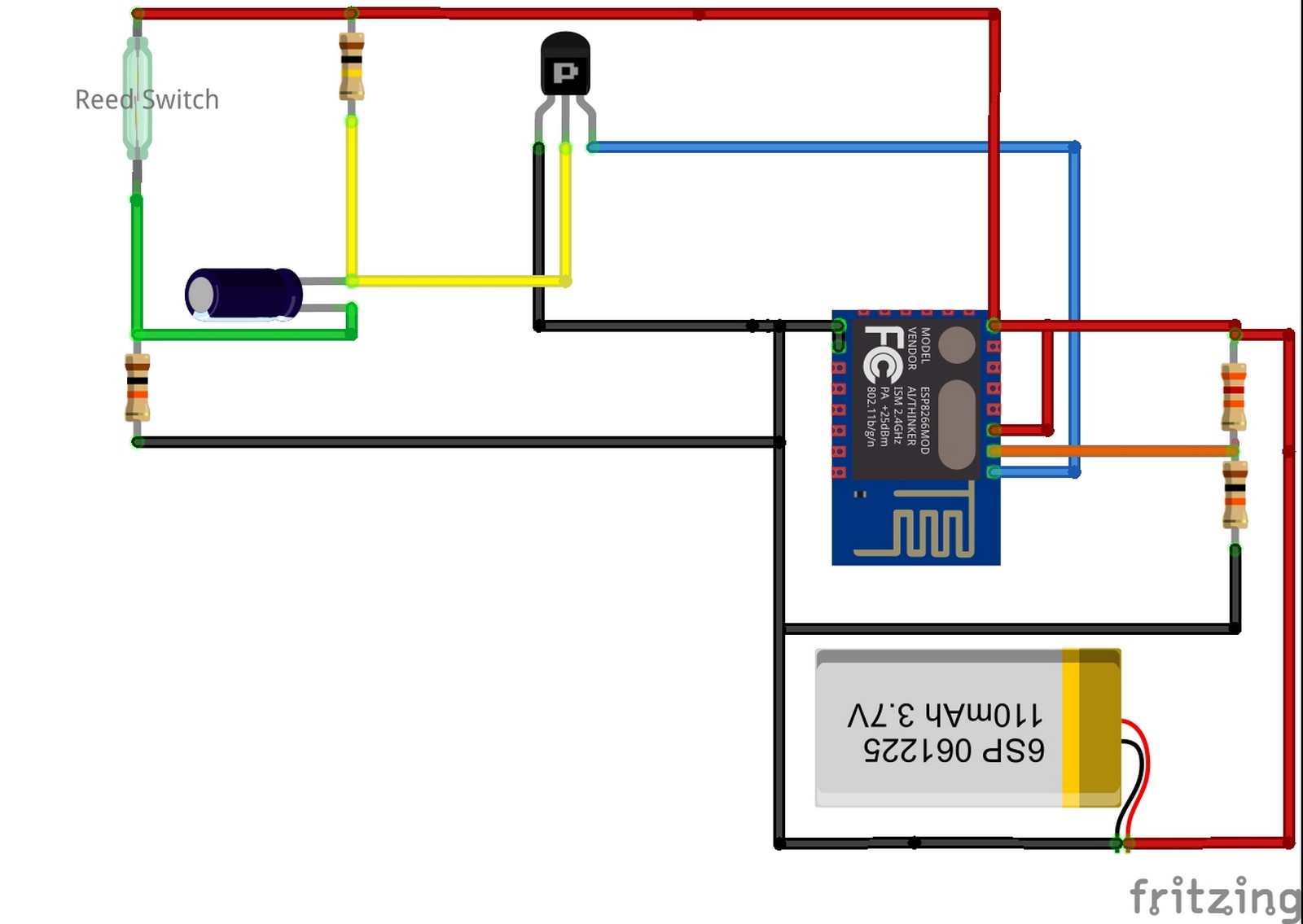
The components on the left of the circuit are:
- Reed switch
- Two resistors 10K, 100K
- 47 uF electrolytic capacitor
- BC557 PNP transistor
The connections to the ESP8266:
- Battery to VCC and Ground.
- CH_PD to VCC
- Pin 15 to Ground
- PNP Collector to the reset pin.
This is Amir's description of how the circuit work's.
Opening the reed switch will close the transistor and then open it after a short time. When the transistor is closed, the reset is HIGH (due to the internal PULL-UP resistor). When the transistor is open the reset is LOW because of the "short circuit" to GND through the transistor. By making sure the left two resistors have high values, almost no current flows through them. (I chose 100K, 10K).
Power Remaining
In addition to sending an email, using the ESP's analog port, a couple of resistors, and a nifty bit of code, the email received also includes the battery voltage - a very significant addition if you're using unregulated 18560 Lithium-Ion batteries (see below) that mustn't fall much below 3v.
This is Amir's explanation of the circuit:
Another nice feature is on the right. Connecting the battery through two resistors, (32K,10K) and between them connect the Analog input of the ESP. The values of the resistors assume you're using a Li-Ion battery but can work with other batteries as well. This circuit gives you a reading of the battery's voltage and by adding two code lines to the Arduino sketch the email you receive will include that voltage too.
The code containing the battery voltage looks like this:
#define BLYNK_PRINT Serial
#include <ESP8266WiFi.h>
#include <BlynkSimpleEsp8266.h>


// You should get Auth Token in the Blynk App.
// Go to the Project Settings (nut icon).
char auth[] = "xxxxxxxxxxxxxxxxxxxxxxxx";
int analogPin = A0;
String stringMail = "The mailbox has been opened! Battery voltage is: ";

void setup()
{
  Serial.begin(115200);
   Serial.println("BEGIN");
   Blynk.begin(auth, "ssid", "password");
}
void loop() {
  while (Blynk.connect() == false) {
    // Wait until connected
  }
  BLYNK_LOG("Switch Open");
  int battlevel = analogRead(analogPin);
  float voltage = battlevel * (4.2 / 1024.0); // 4.2 is the nominal voltage of the 18560 battery
  Blynk.email("xxxxxx@gmail.com", "From Blynk", stringMail + voltage);
  BLYNK_LOG("Going to Sleep");
  ESP.deepSleep(0);
}
When I first put the circuit together my voltage reading was off. Because I didn't have a 32k resistor, I'd used a 28k instead. Amir's reply to my email was this:
You should use the correct resistors or at least the same ratio between them (i.e , 32K --> 10K or 16K --> 5K or 320K --> 100K etc.). Just don't use small value resistors because it will drain the battery. Remember - the current flowing through the resistors is : I = V / (R1 + R2) so assuming V = 4V and using the resistors 32K,10K, you will get I = 4 / (32K + 10K) = 0.1mA = ~100uA
This precise ratio was chosen since the analog input of the ESP can measure only voltages between 0V to 1V. 0V gives you a measure of 0 and 1V gives you a measure of 1024.
The voltage measured in this circuit is V = Vbat * (R2 / ( R1 + R2)), so in our case if the battery is fully loaded at 4.2V you will get V = 4.2 * (10K / ( 32K + 10K)) = 1V --> The measuring is: 1024*1 = 1024 and if it goes to 3V which I believe is the minimum you want, you will get:
V = 3 * (10K / ( 32K + 10K )) = 0.714V ---> The measuring is 1024 * 0.714 ~= 731
Not the end of my problems
I was very close to where I wanted to be. My circuit was working on my prototype board, so I spent an hour soldering things together for permanent use.
When I was finished, I excitedly plugged everything in. My ESP fired up and its little red indicator flared cheerfully. When I opened my reed switch, the email promptly arrived. All was looking great - until I noticed my voltage reading was wrong again.
I scratched my head over the problem for two hours and couldn't figure it out. In the end, I wrote what I thought was a stupid email to Amir, asking if there was a particular order to the resistors on the right of the circuit. I've never studied electronics and I couldn't see how the order would affect the reading.
Amir, with characteristic patience, replied as follows:
Yes the order matters - instead of getting this equation:
V = Vbat * (R2 / ( R1 + R2))
you get:
V = Vbat * (R1 / ( R1 + R2))
I swapped the wires around and everything burst satisfactorily into life.
Getting Connected
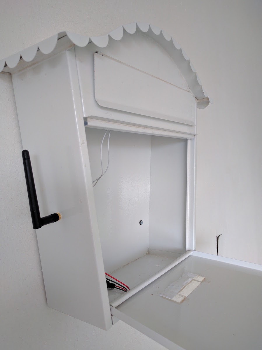
At the outset of this narrative, I explained that my mailbox is in our carport, about 40 steps below me, surrounded on three sides by thick concrete - not the friendliest scenario for WiFi penetration. Added to that, the box is made of metal - and my alerter needed to sit inside, effectively shielding the ESP from every angle.
Another search of the web revealed that the ESP 07 has a connector for an external antenna. Three weeks later it arrived from China - along with an appropriate U.FL to SMA cable and antenna.
Power
An advantage of being electronically ignorant is that I don’t waste time on any single issue; instead, I look for easy solutions, without getting tied to “making it work my way.”
Maker bloggers more knowledgeable than I would spend days figuring out how to power their ESP mailbox alert from a couple of “button batteries” - but I went looking for an easier solution.
Somewhere I’d read that old laptops are a great source of good quality, high performance cells, larger and more powerful than regular AAs. Called 18650s, banks of them are apparently used for powering everything from cell phone charger bricks to electric bikes and cars.
I quickly found an old laptop and pulled its battery apart. (Only after I’d done it did I discover that it’s a potentially hazardous thing to do. An accidental shorting of terminals - all-too-easy to do - could lead to a very dangerous flareup). I managed to scavenge four good cells without incident, learning a lot about Lithium-Ion battery regulation along the way. (For those that don't know, you need to deal with regulation while charging the batteries with just as much care as regulation while discharging.)
Fully charged, my 18650s reach about 4.2V. In my experience, applying this to the 3.3v ESP 12 works just fine. Indeed, I’ve even read that sometimes it’s recommended to use 5v to flash an ESP.
A disadvantage of the ESP 07 is that for some reason its indicator light remains on at all times - even in deep sleep. This considerably saps the power. The solution, I discovered, is to prise the LED off the board, reducing power consumption in sleep mode to almost nothing.
Assembly
When using ESPs, I never solder them directly to a board, choosing to mount them on headers instead. That way, if I need to re-flash or access them, they’re easy to pop out. Mounting them on headers also allows me to place electronics below the board, keeping the whole apparatus small, neat and tidy.
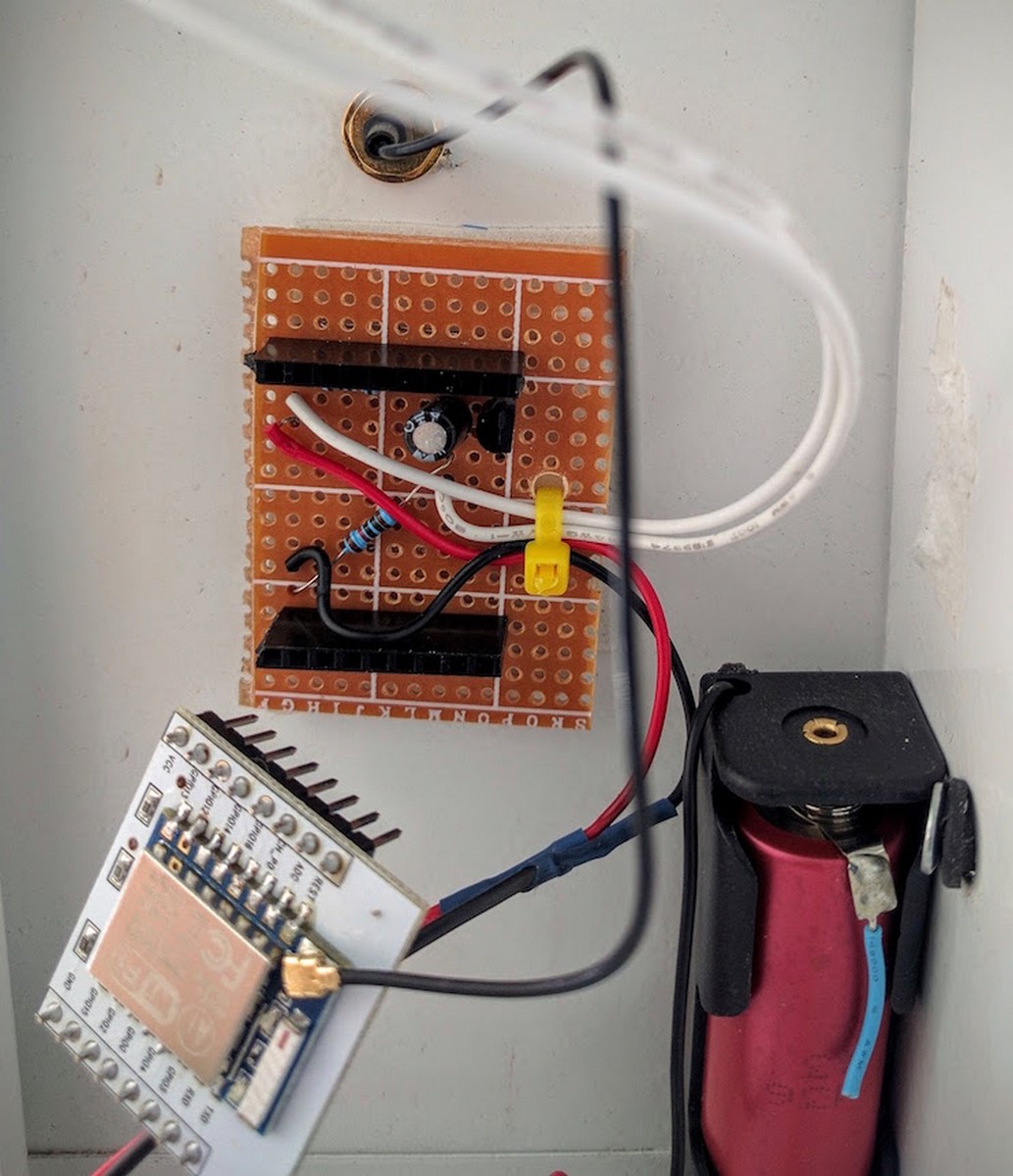
(This photo was taken before I inserted the voltage-dividing resistors).
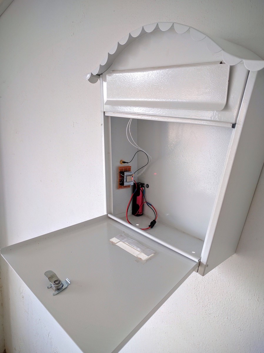
Being extremely light (barely a few grams) the board is stuck to the side of the mailbox with double-sided tape.
The two parts of the reed switch are attached, one on the flap itself, the other on the inside of the mailbox, so that when the flap is lifted, it triggers the switch - which in turn resets the ESP and begins the alerting process.
Addendum
Following publication of this project, I've received valuable feedback from readers - particularly brakeline.
It turns out you don't need a voltage divider to read the battery voltage on an ESP. (The two resistors on the right of the circuit diagram - which can now be excluded.) Instead, you can use the function
ESP.getVcc
For those of you, who, like me, need that spelled out:
First, in the definitions section at the start of your sketch, you'll need to define the analog pin like this:
ADC_MODE(ADC_VCC);
Then, in the text of the email from blynk incorporate:
ESP.getVcc()/10
That should give you the battery voltage. (I used it in another project and it seems to work well. To be honest, I don't know why the result needs to be divided by ten. I arrived at it through trial and error).
The other valuable thing I picked up from brakeline is that using a power source above 3.3v actually reduces the standby time. He suggested using an Ht7333 to regulate down to 3.3v.
Many thanks for all your input and if anyone has more suggestions, please write them in the comments below.
Update - Six Months Later
Since the writing of this post about half a year ago, I've had to re-think one of my claims above.
I mentioned that it's okay to flash an ESP at 5v, but I now understand this is probably inadvisable. My mail notifier worked for several months, but one day suddenly stopped. I fiddled with it for hours trying to identify the problem - which got me reading about the instability of the ESP.
I appears it's extremely sensitive to power issues and it's recommended to use 3.3v only - along with appropriate stabilising capacitors. So please, don't flash at 5v, but read up on best practices on powering the ESP. I found this article very useful.
Update - More that one year later
A few people have had trouble with the circuit and I thought it was time to revisit the project - especially since the world of the ESP8266 has changed so much.
A reminder - I’m an amateur with no formal education in electronics or programming. You’re welcome to read my projects, but they come with “limited liability.” I do seek help when I’m stuck, and I usually get things working, but for truly expert advice you’ll need to look elsewhere. (Some of my fellow bloggers on whatimade.today are true professionals and you can read their material for more detailed explanations).
So what has changed since the original post?
- A lot more is known about the ESP8266. Some very smart people have produced amazing projects, documenting and sharing their knowhow.
- When I implemented my original project there were few ESP development boards available - and they were relatively expensive. I had to solder pins to my ESP, connect it to a USB - ttl adapter, ground GPIO 0 to flash my sketch, then build power circuitry and other hardware to run the project. Now, there are dozens of inexpensive boards that come complete with USB flashing circuity and power management. I’ve more or less abandoned my “barebones” ESPs; it’s easier to install a small development board instead.
Since my original post - and in view of these changes - I’ve taken my concept a little further in my latest iteration. However, to be fair, I need to bring to your attention a YouTube video that more or less makes my project irrelevant. If you want to skip my latest description and go straight to the more efficient version, click here.
My Mailbox - Version 2
Powering the ESP was always a problem. Batteries don't provide 3.3 volts and using something higher requires a regulator like the LM1117. However, the LM1117 has its own dropout voltage and this didn’t work well with the old 4.2v 18650’s I like to use in my projects. Meanwhile, a higher voltage battery wastes energy by LM1117 heat dissipation.
Through regular WiFi dropouts in other ESP projects, I also became aware of the need for stabilising capacitors to keep things running smoothly.
When I came across this video, I realised I may have an answer. Although there’s plenty of criticism in the comments, I made a few of the power regulators and this neat little package works perfectly without a single WiFi dropout.
It pays to have friends
Allan - one of this blog’s contributors - recently started playing with Fritzing to design a board for a mind-blowing project he’ll document in the next few weeks. To give him practice, I asked him to fabricate a circuit board for this project. I sent him the original circuit and told him I’d like to incorporate the HT7333-A, and 1000uF and 100 nF capacitors described in the video. I also told him I’d probably use a Wemos D1 Mini because they are small, cheap, easy to work with - and I had a couple lying around the house. I asked him to include a jumper between pin 16 and RST to enable DeepSleep. (Somehow, that last instruction got lost and instead I got a jumper on the reed switch.)
A couple of weeks later, my beautiful little board arrived. (It was then that I discovered my missing Pin16-RST jumper - but no matter - I could easily solder a wire).
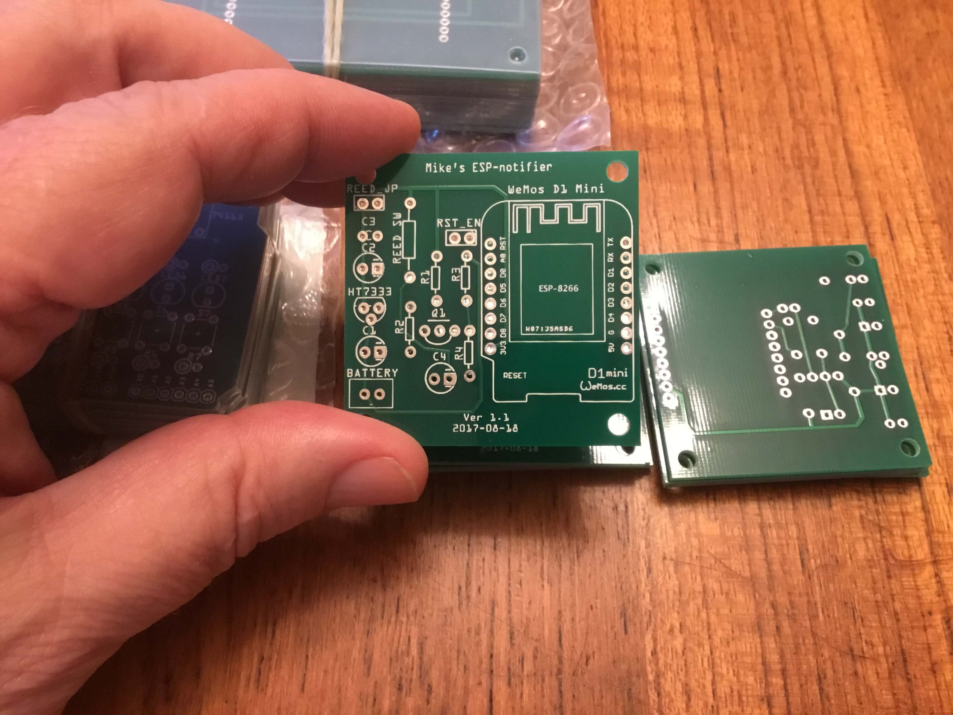
I inserted my components using headers for the Wemos. I did NOT use voltage-dividing resistors - but there’s room for them on the board. I also did NOT run a wire from Pin16 to RST.
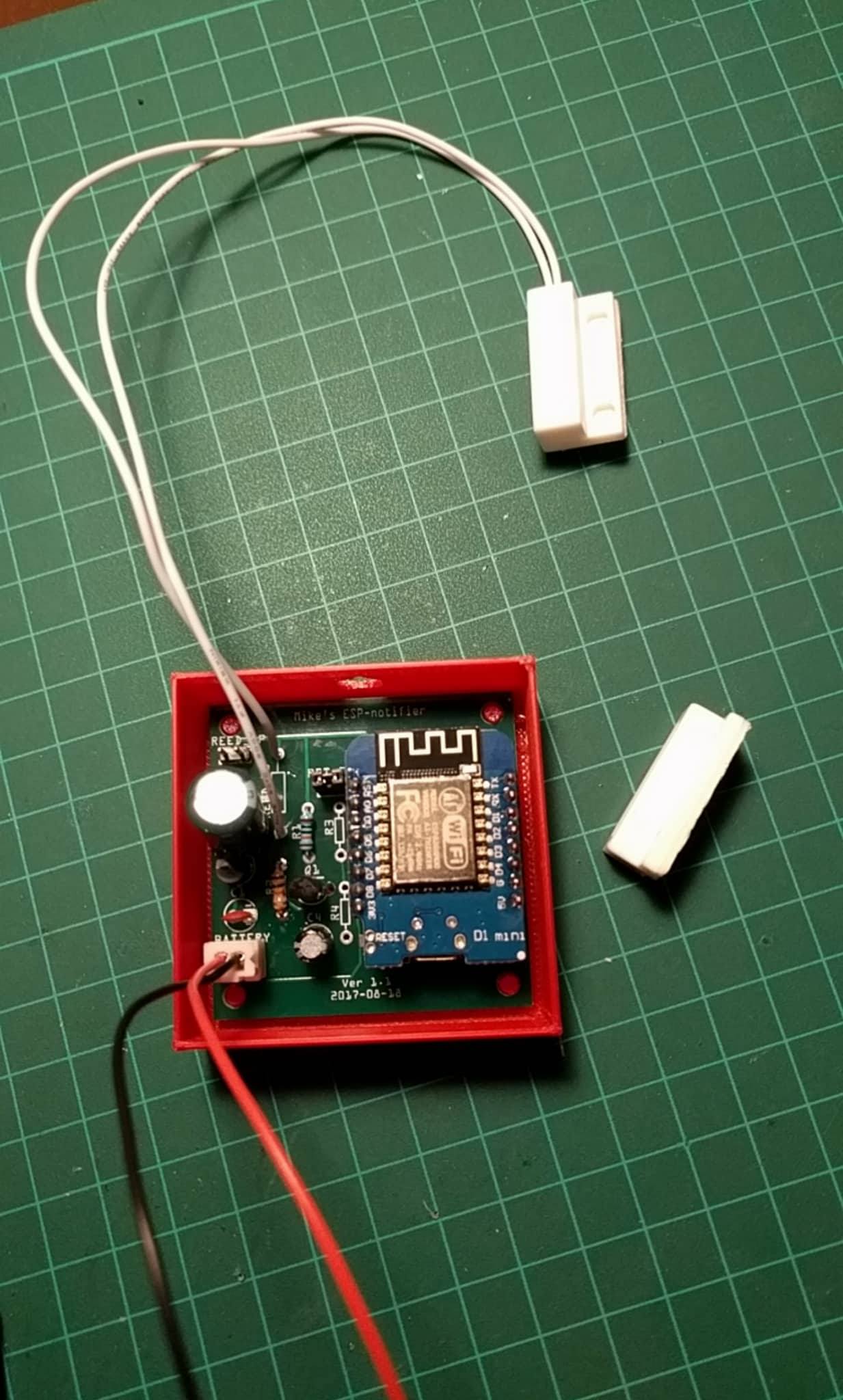
I used a battery pack of 3 AA batteries - about 4.5v - and attached the reed switch and magnet to my front door. It has been there for more than a month and works perfectly each and every time the door is opened. According to
ADC_MODE(ADC_VCC);
the voltage at VCC has not changed since I installed it - indicating (I think) that even without the 16-RST jumper, somehow the Wemos is entering DeepSleep. (Someone with more expertise than me can probably explain this by looking at the Wemos wiki).
So, if you’re still intent on going this route, I suggest you use the Wemos and the HT7333-A with capacitors. The rest of the circuit is the same and works flawlessly for me.
If anyone is interested in the board, let me know. I have only one left but if there’s sufficient interest, Allan could order more. (We’d charge actual production and shipping only.)
Next Generation
The purpose of my original post was to illustrate the use of DeepSleep with the ESP8266 to maximize battery life.
In this brilliant YouTube video, The Guy with the Swiss Accent, shows a very clever way to switch the ESP off altogether. (Thanks to commenter M.6. below for bringing it to my attention). It only powers up when triggered, then stays on just long enough to send its message. It then powers down and waits for the next trigger. Using this method, in theory, the battery life is more or less its shelf-life, minus the few milliamps used each time it is triggered. It could literally last for years.
To implement Andrea's concept, I need to replace my Normally Open (NO) reed switch with one that’s Normally Closed (NC). (See above). The NC reed switch will in fact be Open when next to the magnet. It will close (to complete the circuit) when my mailbox (window/door) is opened. The ESP will do its thing, then power off - all using just a single component (MOSFET) other than the ESP. It’s such a simple idea I’m considering using an ESP01 with the HT7333-A/capacitor for power. The entire package would be tiny - especially if I attach the reed switch directly to the edge of the board. (A nice little project for 3d printing.)
Naturally, my original sketch will require a small, but simple alteration. I’m waiting for the components to arrive and once they do, I’ll post a photo and report of the finished item here.