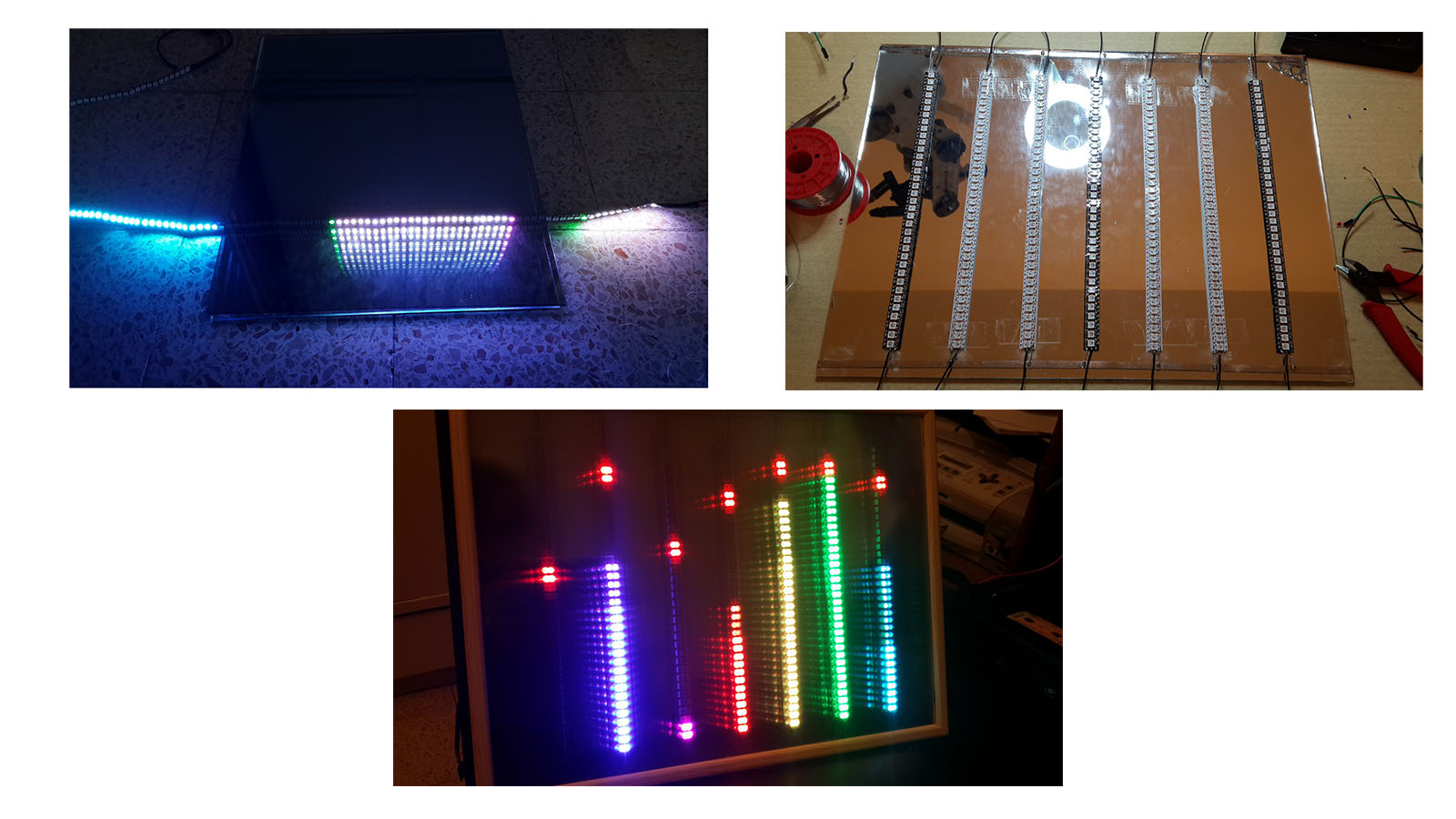
This will be mostly a software post, talking about a new code I wrote for my spectrum analyzer. To get the full hardware description, check part one of this post written a year ago. Here are some photos of from the building process of the cool 3D display:
Most of the new features in the code are on the server side on the web. There's a nice GUI where almost any led and any parameter in the display can be controlled by it. Check this video I made, with the display and the GUI side by side (Best on full HD):
The new code is at the same place as the old one on Github, version 2.0.
What is new comparing to the old version?
- Small hardware upgrade - I've added a volume button to adjust the analog signal from a comfortable spot (And not on board as it was before).
- The old code was written in LUA script. The new code written in C++ using the Arduino IDE environment, and is much faster now.
- The new features:
- Selecting three colors for each octave, and not one color as before, with or without fading.
- Selecting the color of the top leds, which are "falling" slower than the the entire octave levels.
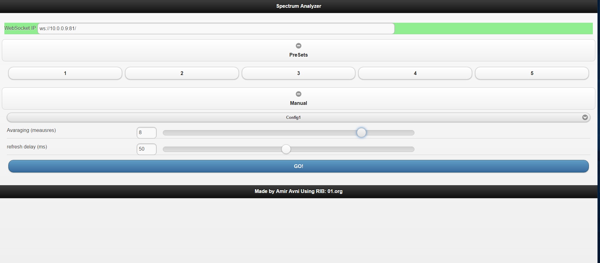
- Selecting the display refresh rate, can be very fast and very slow.
- Selecting the amount of averaging of the analog levels over time, making a smoother changes of the display levels.
- Most important! Controlling each octave minimum noise level. By that I mean what is the minimum analog value where the octave leds will start rising.
- The control is on a server, using websockets - Up to five users simultaneously.
- Update data to all five users when one changes one of the parameters.
- MDNS Support.
- OTA (over the air) updates Support.
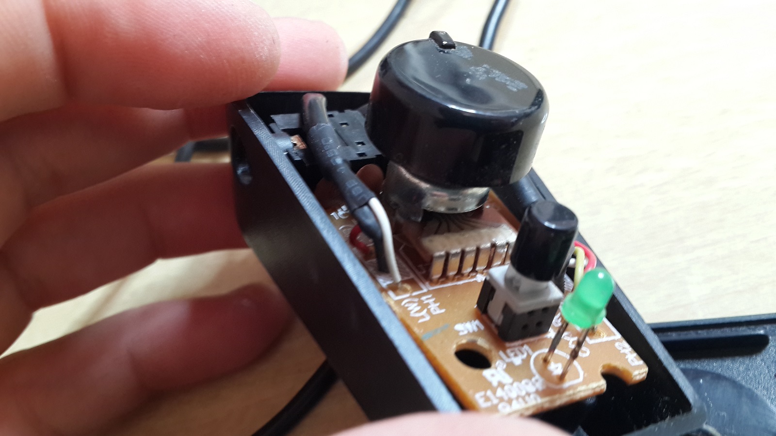
Volume Button
A while ago, my computer's speakers amplifier broke down so I started harvesting parts out of it. One of the parts was a knob for the volume control which was connected by two long wires from the amplifier to the speaker.
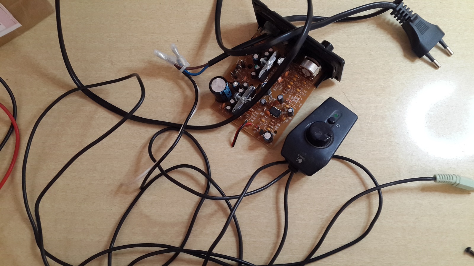
I immediately realize this is exactly what was missing in the spectrum analyzer I've built last year. One of the annoying problems was that I have always had to adjust the volume in the living room, so it will work properly - not too high, not too low. The knob is actually a potentiometer which changes its resistance when turned.
The volume knob was in the middle, with one long wire which ends with an 3.5mm stereo connector and another long wire ends with some wires. All I had to do is check with my voltmeter which wires are the ground, left and right channels and solder them to another 3.5mm connector to have a convenient volume control.
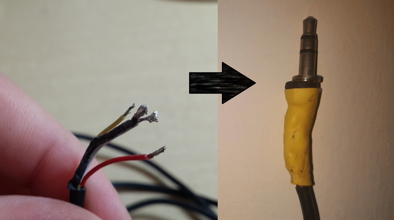
By connecting one side to the amplifier and the other to the display, I could play with the resistance and control the max values of the input signal, thus not really changing the volume but adjusting the display levels to the music.
LUA vs. C++
The code from my first post, the one from last year, was written in LUA script. Since the beginning I was aware it won't be optimal but I was looking for a project to write in LUA so I can get some experience with it. What's the problem with LUA? LUA is a script language, so you can't really control what it does in near-real-time cases. When you use cheap micro-controllers, especially with low clock speed, you should optimized your code as much as possible, so you'll get good performance. LUA is very good for IOT projects - You don't need to know too much about coding to send a request to a web page, get a response and change pins from "low" to "high". However, when you want to refresh a led display things get a bit tricky.
After compiling the LUA script and using many tricks for optimization, I manage to achieve a refresh rate of about 12Hz, which means I could get the audio signal value, divide it into octaves values and change the leds formation once every 80 milliseconds. If you check the video from that project you'll notice that wasn't bad, but still wasn't that fast either.
In my current C++ code, I re-wrote the entire procedure. Before writing the web interface and communication, I started by declaring a pixel and an octave classes, and then writing the display refreshing function. It looks something like that:
void refreshSpectrum() {
  digitalWrite(RESET_PIN , HIGH);
  digitalWrite(RESET_PIN , LOW);

  for (int i = 0; i < 7  ; i++)  {
    myOctaves[6-i].refreshBuffer();
    digitalWrite(STROBE_PIN , LOW);
    myOctaves[6-i].readVal();
    digitalWrite(STROBE_PIN , HIGH);
    delay(0);
  }
  delay(numOfDelay);
  for (int i = 0; i < 7  ; i++)  {
    myOctaves[i].CalcLedsVal();
    myOctaves[i].drawLeds();
    delay(0);
  }
  strip.show();
}
The first thing I've noticed was that the refresh rate was VERY high, around 2-3 milliseconds. Comparing to the 80 milliseconds from before it was a huge difference. It was actually so fast that it looked a bit noisy to me. I didn't know what was the "right" refresh rate for the human eye but I'll get to this issue later. So since it was a bit noisy, I've added a sliding window averaging over 10 samples so the value at a certain time is a combination of the last 10 samples with a chosen weight function. The mathematical function, where $V$ is the final value and $p[k]$ is the analog value for certain 'k' sample, is this:
$
V[N] = \frac{\sum_{k=1}^{N}{k^2 \cdot p[k]}}{\sum{k^2}}
$
Where $k^2$ are the weights. The code implementation:
   void CalcLedsVal() {
      pixelsVal = 0;
      double weightSum = 0;
      double pixelSum = 0;
      for (int iii = bufferSize - numOfHistory; iii < bufferSize; iii++) {
        double weight = (double)(1 + iii - (bufferSize - numOfHistory)) / ( (double)(numOfHistory) );
        weight = weight * weight;
        pixelSum = pixelSum + weight * (double)analogVal[iii];
        weightSum = weightSum + weight;
        delay(0);
      }
      pixelsVal =  map((int)(pixelSum / weightSum), minVal, maxVal, 0, numOfLedsSingle);
}
This sliding window smooths the values and create a nicer look for the display, while still keeping the high refresh rate.
Interface and Communication
On the ESP8266 side
The web interface was the big change in this project and also it made me think on a whole new approach for developing projects such as this one. If you haven't had the chance I would advise reading a post I wrote about a project involving websockets. In short - websocket is great! It is a bit more complex TCP connection protocol but simple to use. From the ESP8266 side there's a very easy-to-use library which supports up to five connections (Can be modified as well), and on the the web side a few simple java script functions is all you need.
On the ESP8266 side, I've added functions for connection, receiving and transmitting data.
void webSocketEvent(uint8_t num, WStype_t type, uint8_t * payload, size_t lenght) {}
When receiving data, I expect to get a string and parse it to get the full command. For example: The next string 2A000255000255255000255000000033050 will be interpreted to:
- 2 - The octave will be divided to three colors (just an "op-code").
- A - The command will be executed on all octaves.
- 000255000 - First color is green (RGB => 000,255,000).
- 255255000 - Second color is yellow (255,255,000).
- 255000000 - Third color is red (255,000,000).
- 033 - Change between first and second colors will occur at 33% of the octave bar.
- 050 - Change between second and third colors will occur at 50% of the octave bar.
So far I described something pretty nice and similar to the last version of this project with some improved features, but lets see what happens when I get this string 5A000255000255172000255000000008050:
- 5 - Change the display config.
- A000255000255172000255000000 - not used.
- 008 - Change the sliding window function to eight samples.
- 050 - Change the delay after refreshing the display to 50 milliseconds, or changing the refresh rate to $\frac{1}{0.05}$ Hz (20Hz).
This last example shows the big advantage when building a project such as that. The main idea in these kind of projects is not to make them practical, but to make them beautiful, so I created a lot of functions with variables following the theory but didn't know what will be the best configuration for these variables. Before using these config strings I had to change each variable, compile and flash the new code and test it. With this new method I can just control them from an external source and understand pretty fast the best and nicest configuration. The most important configuration variable was the noise level adjustment. The analog values the ESP8266 reads for each octave were always around 100-300 (out of 1024) when there was no signal, which means this was the noise level which had to be cut from the display. At first I tried to adjust them manually in the code, but I found that every time I take the display to a different location in my house, the noise levels change a bit. So controlling them online was really helpful.
Another cool feature I added, was executing the next line whenever I got data from any websocket:
webSocket.broadcastTXT(payload, lenght);
This line sent back the data to all the other users which are connected to the ESP8266 through a websocket at the same time, so I could refresh their page and let them know the display colors/configs have been changed. I must give the credit for this feature to Alex who commented on my last post on websockets, suggested this idea and shared his code.
In addition to all the above, I've added OTA support so I could easily flash new code without having to disconnect the display. I wrote a bit more about OTA here
On the web side
On the web side, just like in the post mentioned before, I've created a nice looking website using RIB, and then added the needed java-script functions to the HTML script. Here are a few photos to understand how the GUI looks like, but you can also play it yourself clicking this link (Don't worry it won't connect to my display).
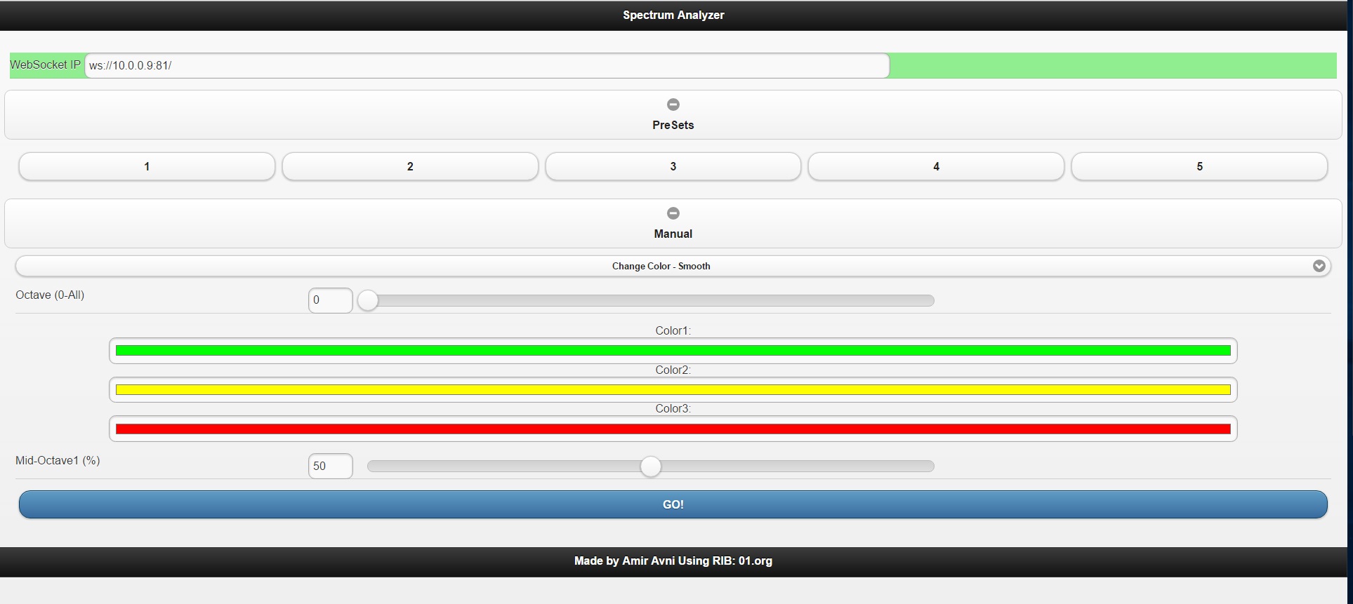
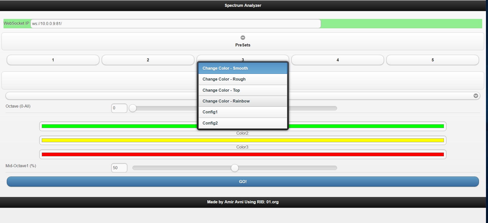
As you see, the interface is very handy, also in mobile view. There are several presets I've created, with color configurations I liked, and a manual section where everything else can be controlled from there. In the background I had to add a few functions to activate the websockets. This is the main function to connect to the websocket, after selecting the right IP and port:
function WSConnect(){
var text = document.getElementById('ip').value;
ipValue = text;
connection = new WebSocket(ipValue, ['arduino']);
connection.onopen = function() {
    document.getElementById("webSocketCell").style.backgroundColor = "lightgreen";
};
connection.onclose = function() {
    document.getElementById("webSocketCell").style.backgroundColor = "red";
};
connection.onmessage = function(evt) {
        console.log((evt.data));
        bigString2Vars(evt.data);
        updateHTML();
};

console.log(text)
console.log("IP value changed to:"+ipValue);
updateHTML();

}
After getting IP and port, it opens a connection, and defines what to do if
- The connection is open - Change the IP cell background to light green.
- The connection is closed - Change the IP cell background to red.
- Message received (from broadcast, as explained before) - Turn string into variables and update the page HTML to the current configurations.
When the user clicks "GO" or selecting one of the presets, the next lines are executed
bigString2Send = bigString2Send.concat(generalVal,octaveVal,color1.red,color1.green,color1.blue,color2.red,color2.green,color2.blue,color3.red,color3.green,color3.blue,var1,var2);
console.log(bigString2Send);
connection.send(bigString2Send);
The string is created using all variables, and then is sent through the websocket to the ESP8266.
The rest of the functions are many java-script operations I learned on the fly (Didn't have too much experience with java script before), you can check them all here
Hope you enjoyed the post! If you have suggestions for more features to make my display cooler or just have questions write them on the comment section or on our Facebook page.
AA