Not all of my projects succeed. Lately I've been working on several different projects which I hope will be documented soon, but last night I've tried to make a pretty easy hacking project which unfortunately didn't end as I expected. Still, I was very close to make it work and learned some things on the way, so why not documenting.
It all started with a mail order I received - Four boxes of these items. This is a lamp, which can be plugged to a common lamp socket, and has a RGB 20W Led which can be controlled via an IR remote. I plugged it in the living-room, tried it and was happy - It really gave a new atmosphere to the living-room. Then, the next thing I thought was - Why controlling it with a remote and not with the phone/laptop? It shouldn't be that hard to do so. This is how it looks like by the way:
The safe way to do so was to copy the IR signals and write a code to an ESP8266 which receives commands from the internet and sends the right IR signal to the lamp. But I chose to go with a more interesting way.
The electronics inside the lamp were probably already most of what I needed. I planned to simply add an ESP8266 to the process (Instead of the IR circuit) and connect it to the internet. I already had a program and a web site to control RGB light so basically there was almost nothing to do.
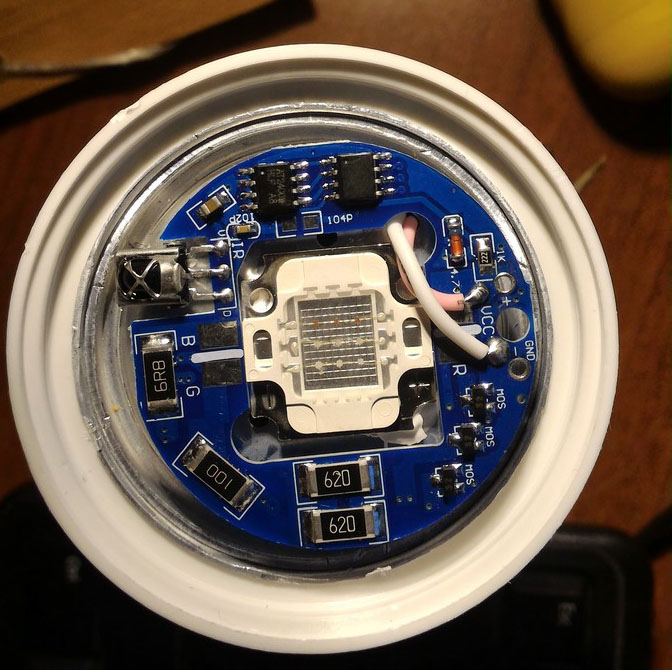
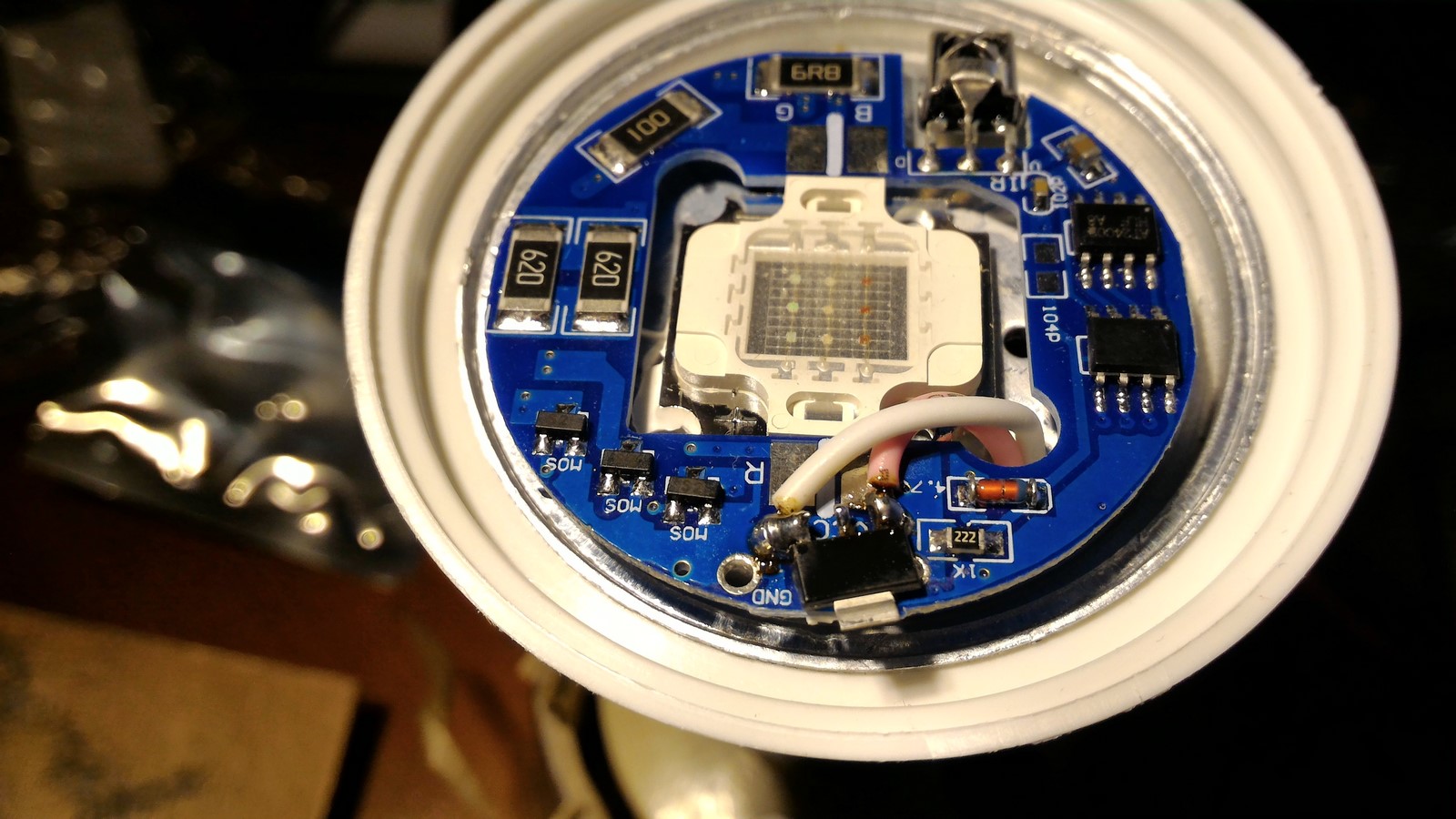
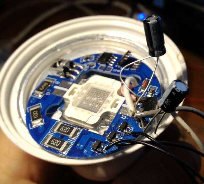
It seems to me like a few hours job, and the weekend has just started so I went for it. I've started with disassembling the lamp and analyze the components. Here's how it looks like on the inside:
The Analysis
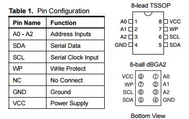
Let's understand what really happens when we plug this circuit to the outlet. Checking the chips on the board, it seems there's one chip with no writing at all, so we cannot know what is it. Another chip with the writing AT24CO2. Googling this one and we see it is an EEPROM with the next description:
After some measures and reasonable assumptions I got to the next facts:
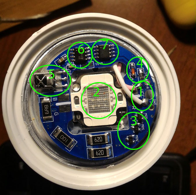
- The pink and white wires are coming from the bottom of the lamp and are connected to an AC/DC converter. They produce around 12VDC with some small AC voltage.
- RGB led, a very powerful one, connected on the left and right parts of the board for each of the 12V/R/G/B connections. The bottom of the led is connected to the cover for cooling. The leds are connected from one side to the 12V (#1) and from the other side each color is connected through a resistor to the collectors of the MOSFETs (#3).
- Three MOSFETs to activate the RGB led. The collector is connected to the leds (#2), the emitter to the ground (#1), and the base to one of the legs of the micro-controller (#7).
- The 12V voltage (#1) goes through what looks like a resistor and a diode. At the other end of the resistor there's voltage of exactly 4V. This voltage is supplied to the IR receiver (#5), the micro-controller (#7) and the EEPROM (#6).
- IR receiver with three legs. It is connected to power and ground (#4), and the third leg is connected to one of the legs of the micro-controller (#7).
- AT24CO2 EEPROM - This EEPROM gets 4V power (#4), and has I2C communication with the micro-controller (#7). Only two legs (SDA,SCLK) are connected to the micro-controller and besides the VCC all other legs are connected to ground.
- Finally, this is probably the micro-controller which I know nothing about since there's no writings on the chip, but checking the connections of each of its legs can say a lot about what it does. There are eight legs which are connected as follows:
- 4V-VCC and Ground (#4)
- Two legs are connected to the SDA and SCLK of the EEPROM (#7) so these legs are most probably digital I/Os.
- One leg is connected to the IR third leg (#5) so this leg is most probably an analog input.
- Three legs are connected to the three bases of the MOSFETs (#3) so these legs are probably digital I/Os which supports PWM.
After understanding all of this, it is pretty obvious what this circuit does. The micro-controller receives a command from the IR remote, requesting data from the EEPROM due to this command, probably RGB 0-255 data, and write this data using the PWM to the three legs which are connected to the MOSFETs bases, thus controlling the RGB intensity and creating the wanted color. Pretty cool gadget for a few dollars.
The Hacking
If you've read my post on the living-room RGB lights, you should understand by now that I already have most of the electronics and code I needed. All that was left was to upload the ESP8266 the same code and bypass the other micro-controller.
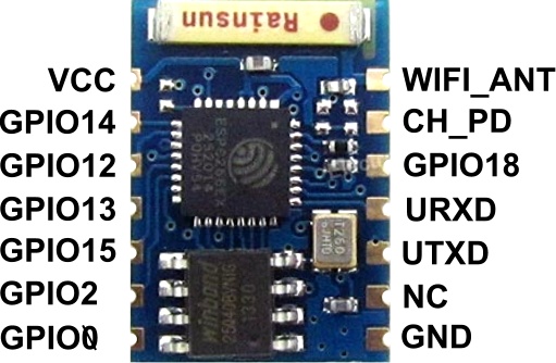
I decided to use for the first time the ESP8266-03. This version of the ESP8266 is one of the smallest I know but it still has the needed amount of GPIOs. This is the GPIO diagram of the ESP8266-03
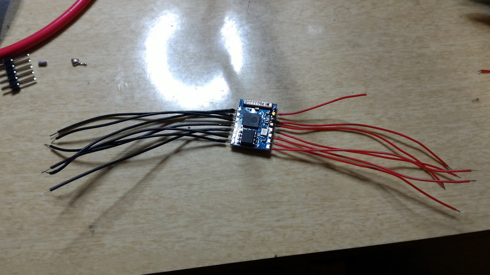
One of the pins is for an external antenna. I decided to use it since the WiFi in my work room is not very good. The antenna should be a wire with length of a quarter wave length of the WiFi wave length. The calcultions are:
$$
\frac{\lambda}{4} = \frac{c}{4 \cdot f} = \frac{3 \cdot 10^8 }{4 \cdot 2.4 \cdot 10^8} = 3.125 cm
$$
where $c$ is the speed of light and $f$ is 2.4GHz, the WiFi frequency. After soldering all the wires to the pins, I made sure the antenna's wire is around 3.125 cm.
Next, I've added some pins and a flashing button to ease the flashing procedure, and connect the usual pins:
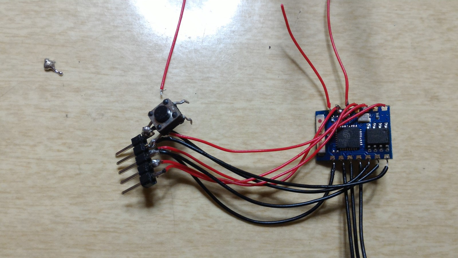
- GPIO15 --> GND
- CH_PD --> VCC
- GPIO0 --> Button
- TX
- RX
Then I flashed the same code I used in my other post without any problems. I entered my website, tested the ESP8266, everything worked great.
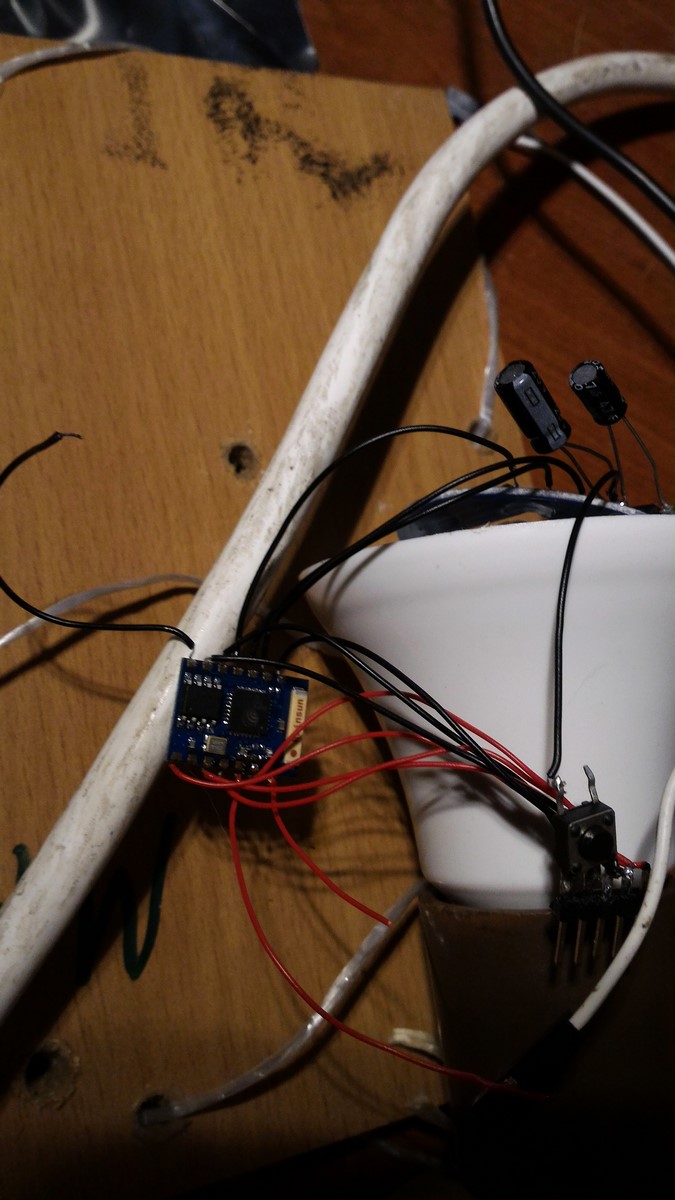
The next step was to prepare the connections on the circuit. I've added AMS1117 voltage regulator, which can reduce 12V to 3.3V, and soldered it to the 12V and ground connections.
Then, I measured that I truely have 3.3V and I've noticed there's also some AC voltage, about 400mV. So I've added two capacitors, one before the regulator and one after the regulator. After that there was still 100mV AC voltage which I guessed wasn't a big deal (After all, the DC voltage was stable enough to power another micro-controller).
Also can be seen in this photo, that I've added wires to the bases of the MOSFETs, and solder out the old micro-controller legs to the MOSFETs.
The next step was to connect the GPIOs of the ESP8266 and test the new circuit. I started by powering the ESP8266 from a USB cable, powering the circuit from the outlet and creating a common ground between them. Testing it and it actually worked great! About two hours work and everything worked just as I expected! Which means I could control the lamp's color from the internet.
I usually have a video of the project working at this point. This time I don't, and in the next section you'll see why.
The Failing
The last step was to power the ESP8266 from the circuit itself, close the plastic cover and enjoy! Wasn't expecting any issues, I connected the VCC to the 3.3V on the circuit and connected the lamp to the outlet.
Then, the LED started flickering, and the ESP8266 did not connect to the internet. Also it became very hot. I tested it again with the USB cable and it didn't work anymore. I started testing the pins on the ESP8266 and noticed the VCC and GND are at short-circuit. Then I realized that either one of the capacitors on the ESP8266 board have been burned or the entire micro-controller has been burned. I couldn't understand why it happened. I assumed it had happened because of a voltage peak from the lamp circuit, but I thought I took care of it with the capacitors.
So I changed the capacitors to bigger ones, assuming it will solve the problem, took another ESP8266, soldered everything again, uploaded the program, powered it with USB, tested it to see everything is OK, connected everything together and AGAIN!! The ESP8266 has been burned.
Since I don't have a scope, only a fluke, I could not detect if there were any high voltage peaks from the power source. Also, I don't know which micro-controller was used before so can't go and check how come that one was working fine.
So after two hours of building, and three hours more of fighting I decided to back off. I soldered out all the wires, soldered back the old micro-controller and decided to stay with the current lamp. Still, it wasn't a waste of time, it was fun to try and do some reverse engineering to someone else's circuit. Perhaps I'll find some time in the future and just make a micro-controller which copies the IR signals of the remote, that should definitely work.
AA