This post explains how I ended up manufacturing a cute little binary counter PCB through jlcpcb.com.
To make it clear from the start - my only connection with the company is that I've ordered a couple of PCBs from them. I'm simply amazed that they can offer the service they do for the price they ask. In the past I'd spend hours trying to make my own PCBs, juggling with hot irons, transfer paper, limb-threatening acids, and 80% fail-rates. Almost by mistake (you'll see below), I found myself ordering from jlcpcb.
No more DIY PCBs for me - not only do my modest little boards look great quality, but the turnaround - even by airmail - gets the PCB to me at the other side of the world within a couple of weeks. About $10 (including airmail shipping) for 5 custom PCBs seems to me to be outstanding value.
If anyone's interested in my files, let me know in the comments and I'll find a way of getting them to you.
Seven Segment Display
A while back I decided to make use of four large 7-segment displays that I bought in a garage sale a couple of years ago.
Each 7-segment has 10 pins - that's 40 pins altogether - way too much for the Arduino Nano I wanted to use.
This got me on to examining the use of a decoder. The idea is to use four pins of the decoder to produce numbers on the LED. I'll be using the SN74LS47N because my LEDs are common anode. Normally, I'd have used the popular MAX7219 that co-blogger, Allan has written about extensively, but it only works with common cathode LEDs.
The Decoder
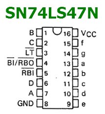
Notice the pins B,C,D, and A on the left of the chip and the letters f,g,a,b,c,d,e on the right.
The letters on the right correspond to the standard segment lettering of a 7-segment display:
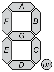
The four pins B,C,D, and A can be turned on and off using an Arduino to create the required digit on the 7-segment display.
But how do you get 10 possible numbers (0-9) from just four input pins?
Binary Counting
Let's count to 15 using binary:
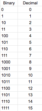
As you can see by the column on the left, by using four pins, it's possible to represent up to 16 decimal numbers - so getting to only 10 is a cinch.
Making Arduino count in binary
So while I was waiting for my decoder chips to arrive from Aliexpress, I got to thinking how I can make my arduino count in binary. Instead of counting 1, 2, 3, 4.. it would count 0, 1, 10, 11, 100...
It didn't take long to discover this smart little piece of code.
// we will use Arduino pins D2, D3, D4 .. D9
int ledPin[] = {2, 3, 4, 5, 6, 7, 8, 9};

void setup()                 // setup the Arduino pins
{
  for (int i = 0; i < 8; i++) {
    pinMode(ledPin[i], OUTPUT);
    digitalWrite(ledPin[i], HIGH);
  }
  delay(3000);               // 3 second lamp test
}

void loop()                  // main loop to count to 256
{
  static byte counter = 0;
  displayBinary(counter);
  counter += 1;
  delay(1000);
}

void displayBinary(byte value) // display the binary number
{
  for (int i = 0; i < 8; i++)
    digitalWrite(ledPin[i], bitRead(value, i));
}
This would count to 256, outputting in binary to the Arduino pins. (This means it will turn the pins, A, B, C, D, on an off sequentially in the order of the table above).
Making a cute binary counter
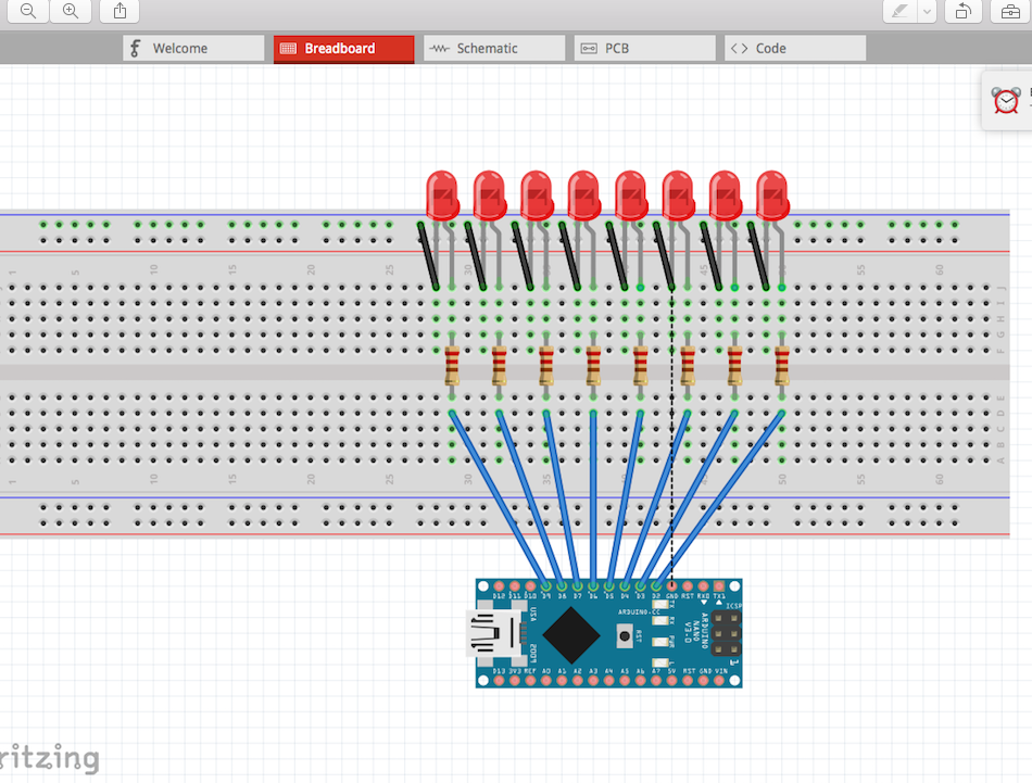
I got to thinking this would be an excellent project for my very first PCB; the board would have only an Arduino nano and eight LEDs (with current-limiting resistors).
I put it together quickly on Circuits on Tinkercad to see if it worked. I ran the code and watched with satisfaction as the binary lights blinked on and off.
Designing the PCB on Fritzing
Next step was to design a PCB. I'd used Fritzing before, but only for breadboarding. I'd never tried the PCB side of things.
So I set up the same breadboard as I'd done in Tinkercad.
Then went over to look at the PCB side.
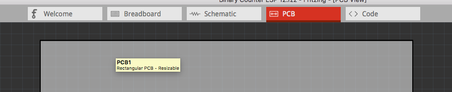
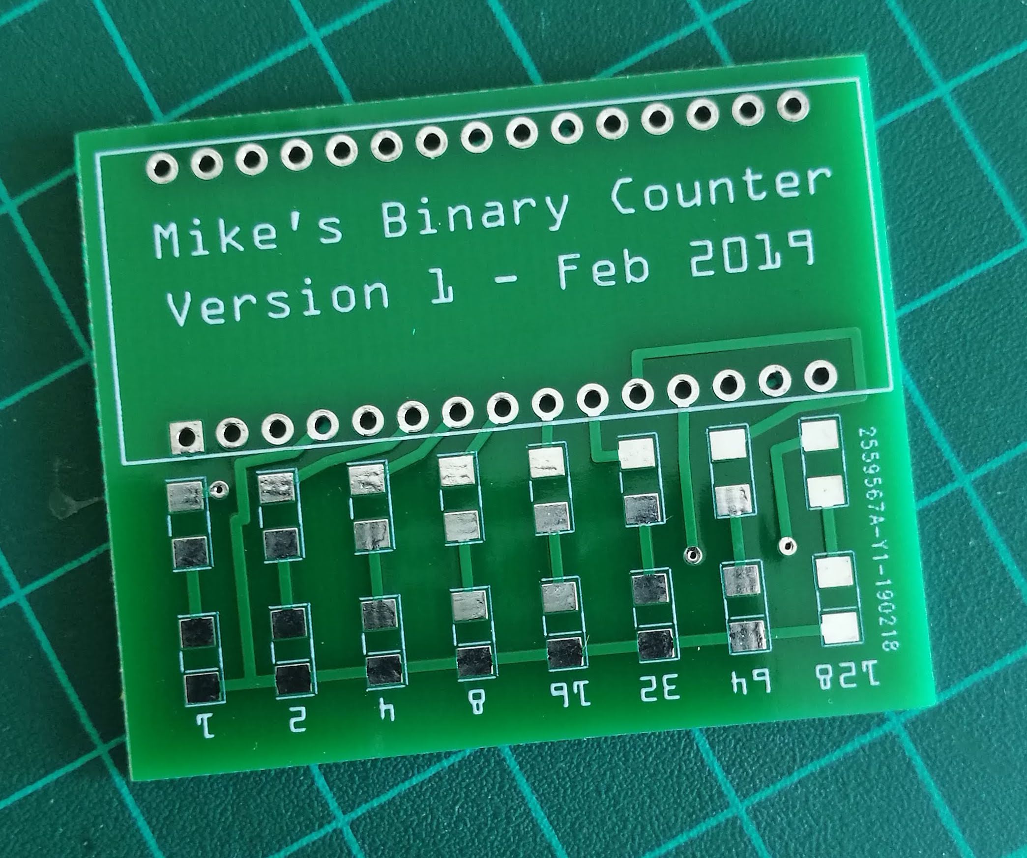
It took me a couple of hours to understand how to move things around, connect them up, use "vias" to move from one side of the board to another - but like everything else, with a few YouTube videos and a bit of practice it all began to make sense. (If you look at the header photo of this post, three vias are clearly visible. At this point, the trace moves to the other side of the board.)
Through hole or not through hole?
I've become an enthusiast for surface mounting (SMD) components - principally because I get a kick out of their size; it amazes me that we can make working components so small you can barely see them.
So I decided to ditch through-hole LEDs and make my Binary Counter as small and neat as possible.
This is what my finished SMD board looks like in Fritzing. I used size 1206 components because they're the smallest I can comfortably solder.
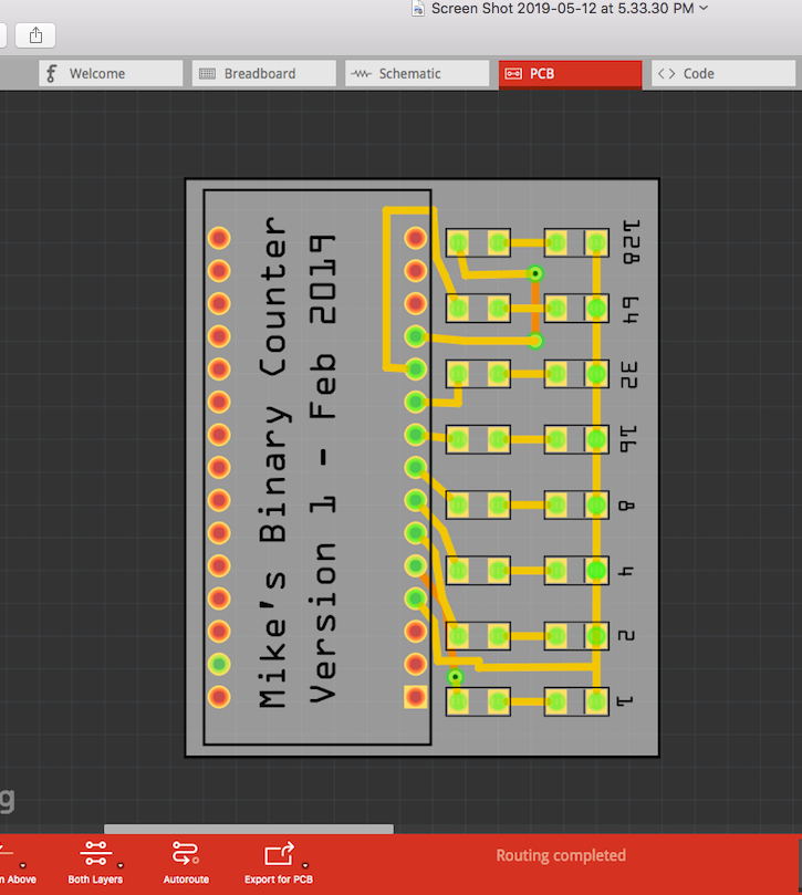
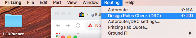
Once I had it the way I wanted, I ran "Design Rules Check" to make sure none of my lines crossed where they shouldn't.
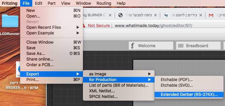
After I got a clean bill of health, it was on to exporting as Extended Gerber (RS-274x).
Jlcpcb
Once you've exported the Gerber files, it's time to import them into jlcpcb.
I've got to hand it to them. The process of uploading and ordering your board is so simple, even a complete novice like me can do it.
First, open an account.
Then, create a zip of your Gerber files. Once you have it, click "Quote Now" and upload your zip. Once it's uploaded you can tweek it and view it, but in general, that's all there is to it.
Pay a few bucks and wait for your boards to arrive.
Will it work?
I waited excitedly for my package to arrive. It was my first PCB and I'd no idea if I'd done it right. Were my traces right? Did I make proper Gerber files?
When the package finally arrived, I split open their vacuum-sealed bag and examined my boards. They were exactly as I'd designed them - down to my little decimal numbers and my name and version printed between the Arduino pins.
I quickly whipped out my TS100 and tweezers, fluxed my contacts, and soldered my little components in place.
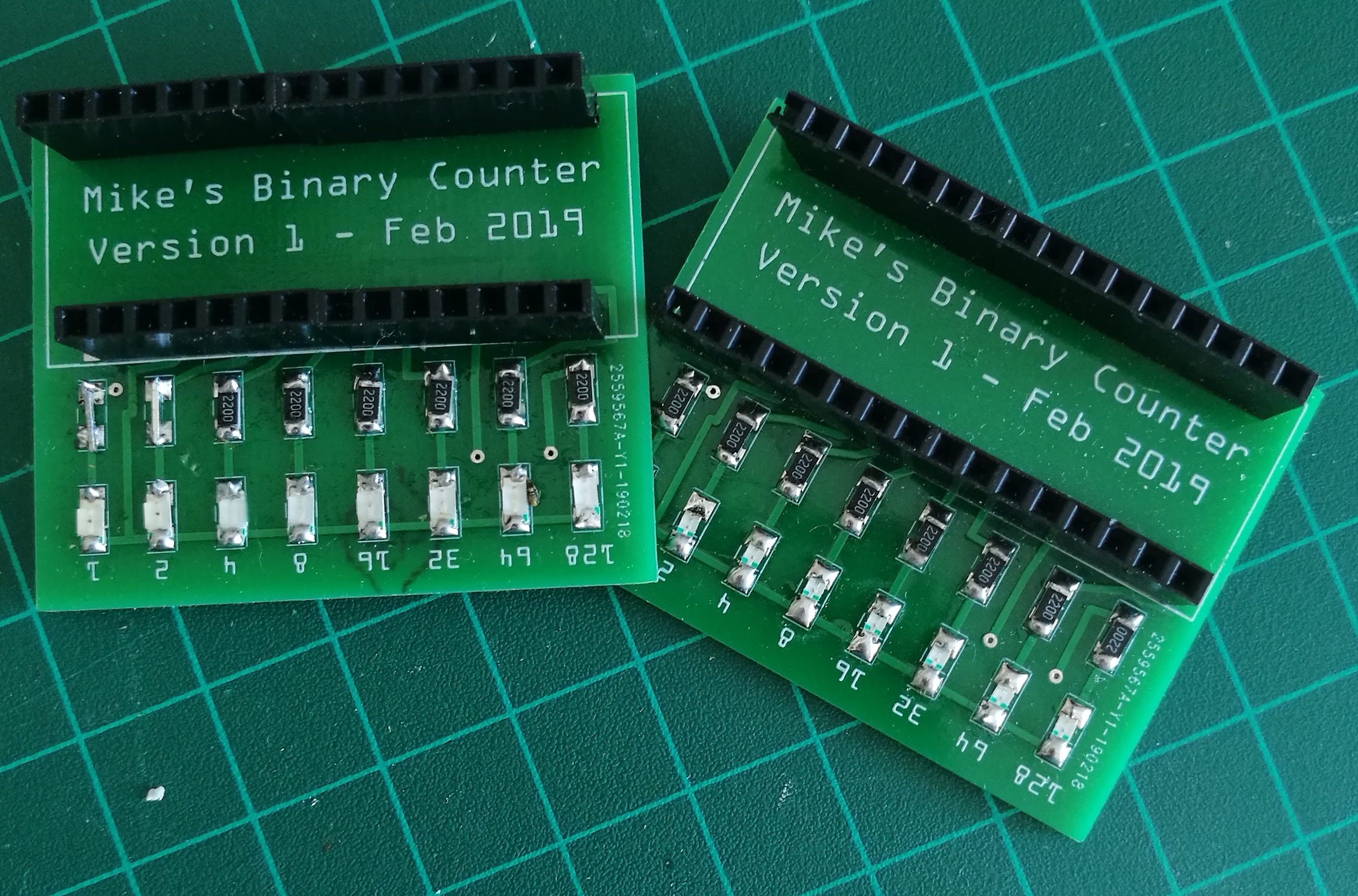 The version on the left has multi-coloured LEDs. The one on the right is blue LEDs only. I put headers on the board so that I can move the Arduino between them. (The red version I used in the video at the top of this post has the Arduino soldered directly on the board to make a really small package. It's powered by a 9v PP3 battery on Vin.)
You'll notice the one on the left lacks left-most resistors. This is because these two LEDs are purple and very dim, even without resistors.
Didn't I digress? What about the SN74LS47N decoder?
Well, yes, I did digress. You see, that's what happens when you fiddle with electronics. One little project leads to another.
This post was my introduction to the subject. My next post will explain how I took the SN74LS47N and incorporated it into another jlcpcb board along with the 7-segment LEDs to create my LCD counter. Watch this space.