Generally at whatimade.today we post original projects we dream up ourselves. Today's post is a little different. We're going to describe how we constructed Mirko Pavleski's single-digit clock. We made it because it's a fun project, wonderfully impressive to look at, and a great design. Not only is the idea original, Mirko's stl files for 3D printing are excellent, and his coding for the Arduino is very, very, sophisticated.
We admired the project so much we took it one step further. Having observed the birds' nest of wires trailing all over our breadboard, we decided to create a PCB to make the project neater. Read on.
Components
The original components are clearly itemized in Mirk's hackster project page and we'd encourage you to go there to give him the traffic he deserves. One extra component we used is an L7808 voltage regulator (with supporting capacitors) that you can read about further down.
Making it on the breadboard
While our 3D printer layered out the single digit, we constructed the circuit on a breadboard.
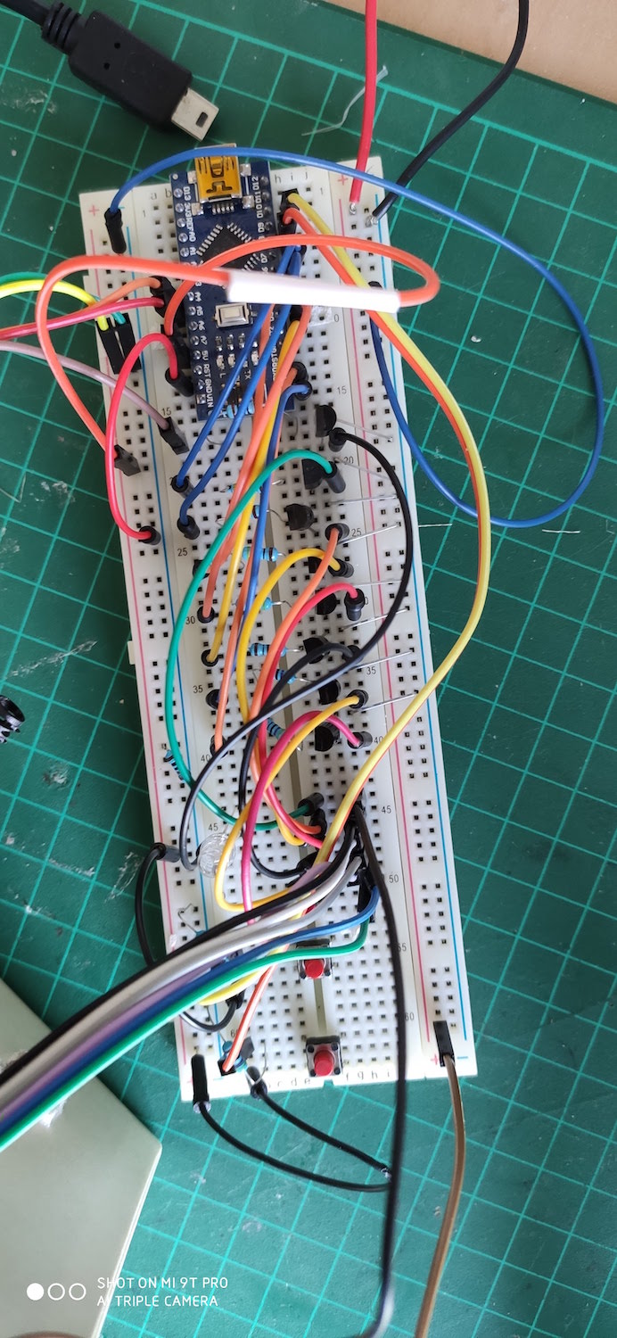
Looking at the layout you'll see there are a heck-of-a-lot of wires. (There would be even more if I hadn't used staples to run the eight transistors to the GND rail.) I always have problems with Dupont wires; sometimes the heads fall off, and sometimes they simply don't make good contact with the breadboard. The more wires, the greater the chance of the circuit not working - and this project was no exception.
To get around recurring problems and because I wanted a compact little board, I decided to make the same circuit on a stripboard.
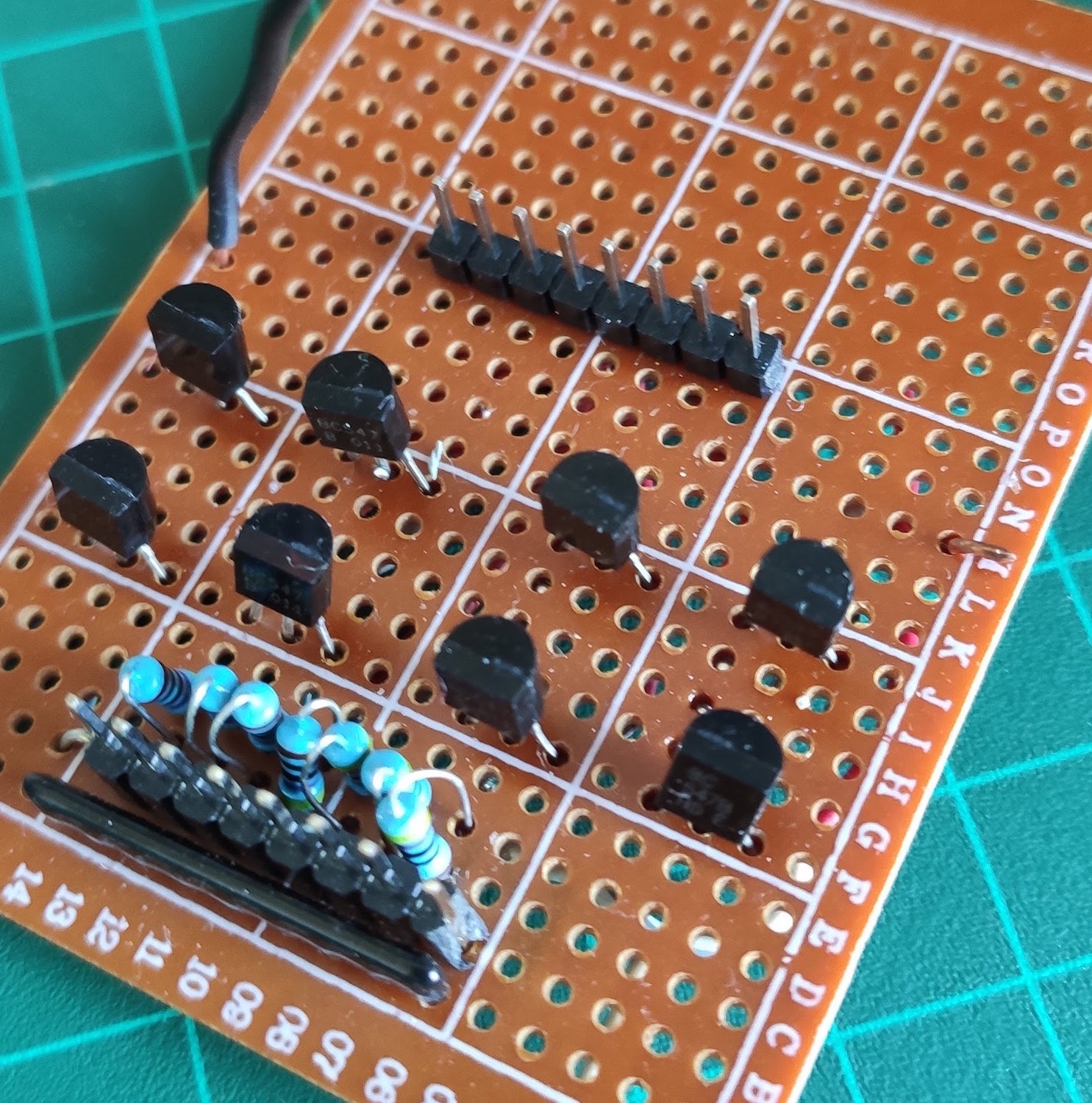
Although it looks fairly simply from above, I'm too embarrassed to show you the underside. Let's just say it's not my proudest soldering job and I eventually gave up and went looking for another solution.
5 volts or 12 volts?
I'm actually not sure why Mirko used 12v LEDs. Using 5v LEDs would cut down the complexity considerably, but I ended up using 12v because that's what I had lying around the lab.
For those who don't understand, the BC547 transistors in the circuit are used as simple switches for the 12v power to the LEDs. This video is a similar project using 5v addressable WS2812B colour LEDs instead.
Wiring the LEDs
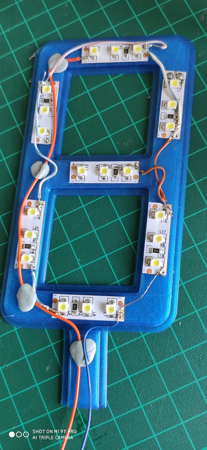
This was by far the hardest part of the project. In the photo below you'll see some terrible soldering - and what you see is only part of the wiring. In addition to the wires in the photo, I had to lead a separate wire from the -ve of each segment out of the base. By the time I was done, there were far too many wires and holding them in place while I tried to close the housing was very fidgety and annoying. In the end I used bluetak to hold the wires while I placed the "lid" on the 7-segment housing.
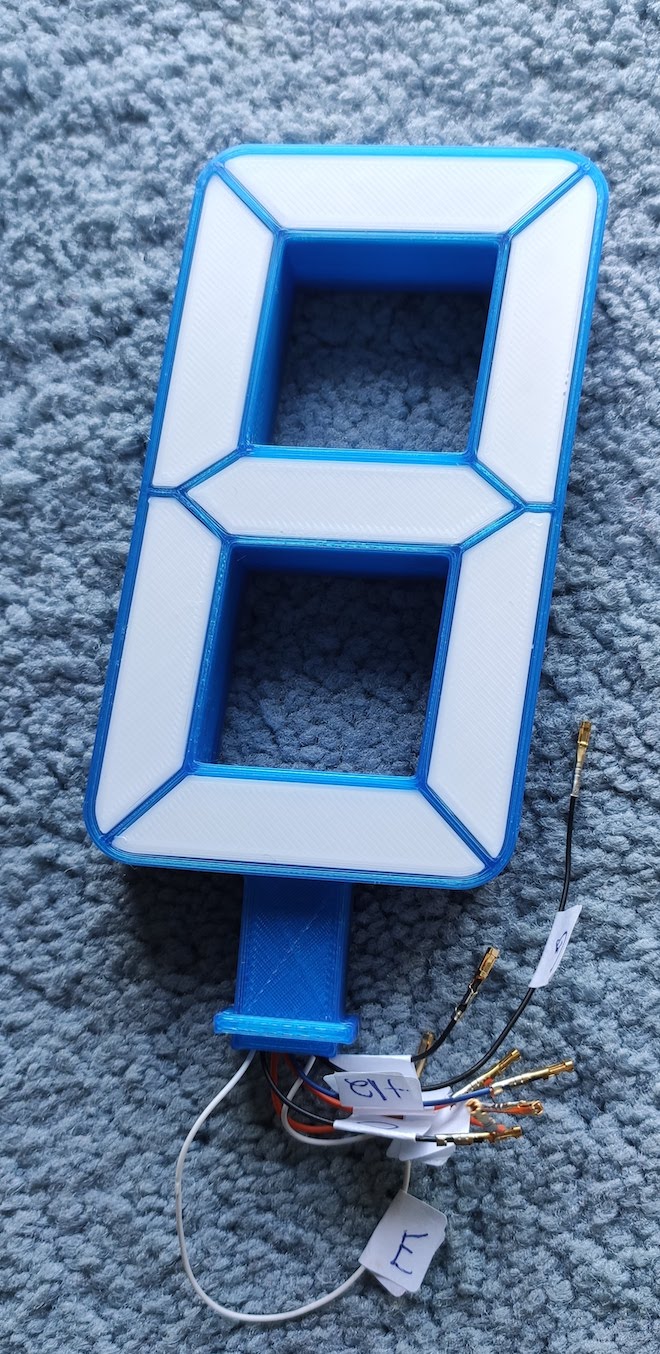
Here's the completed display. Notice the labelled wires emerging from the base. A,B,C,D,E,F,G correspond to the conventional segments of a 7-segment display. I also crimped female Dupont headers onto the wires for ease of connection.
Making the PCB
Readers of this blog know we usually use JLCPCB to manufacture our boards. This time was no exception. They do a terrific, no-fuss job and it's so easy to produce great boards for very little outlay.
I've written before that co-blogger Allan Schwartz is never satisfied with my traces when I produce a PCB, so the deal I made with him this time was that I construct the 7-segment part of the project, and he design our board.
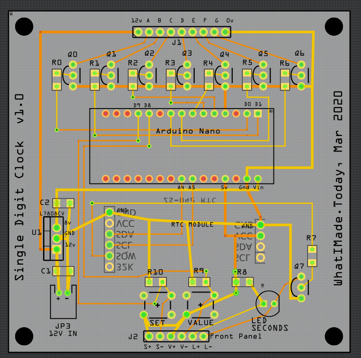
I've described the process before for making a board but anyone wishing to refresh their memory can take look at this post. Using Fritzing we lay out the board, then create Gerber files to manufacture our PCB.
Once that's done, we lay out the PCB. Some of you will complain that "you never put right-angled traces on a PCB." We're aware of this, but voltages are so low and this is just a fun project, so Allan kept it simple.
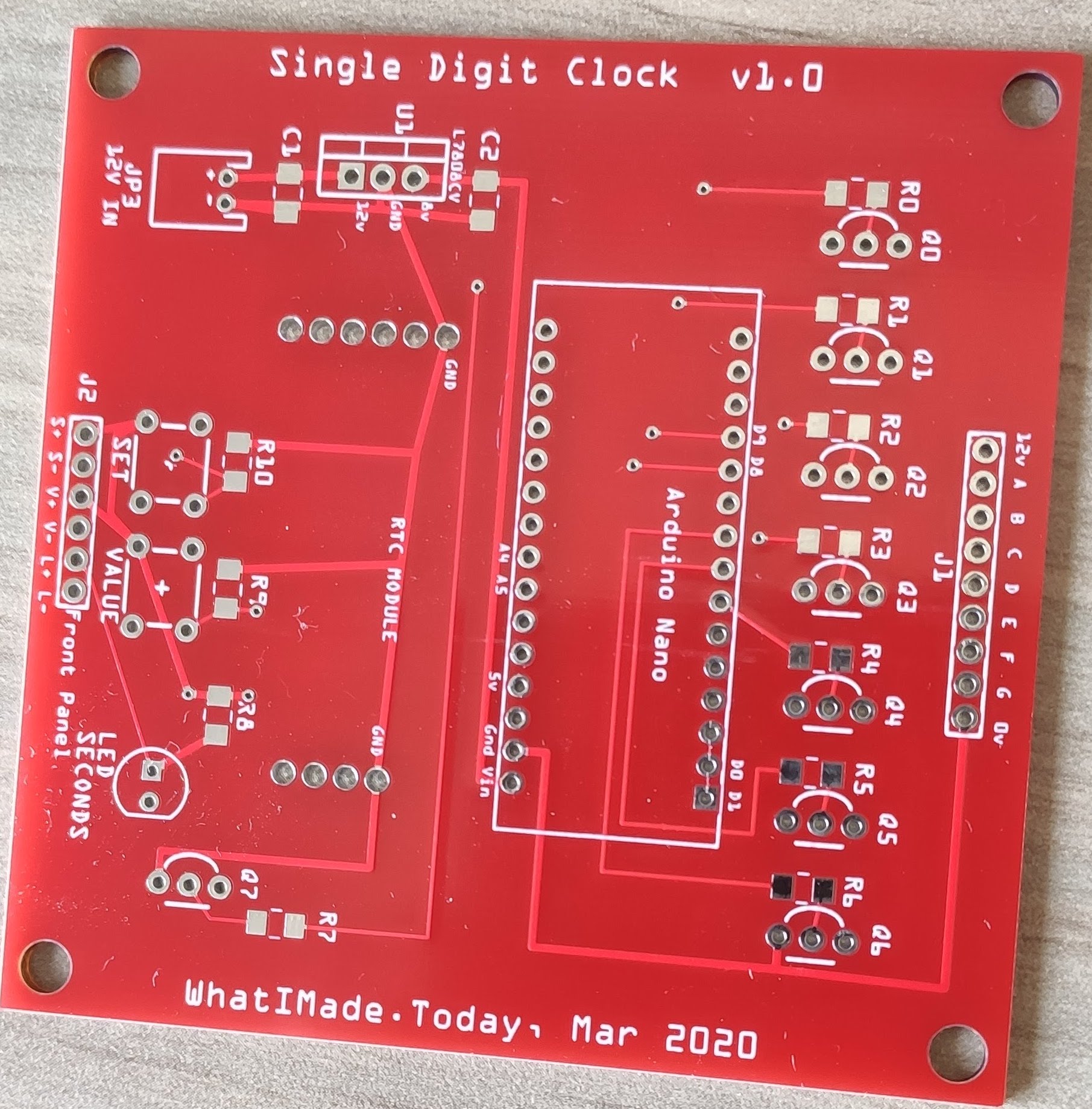
I was delighted when the final product finally arrived - delayed for several weeks by an inconvenient pandemic. I'd chosen a red board this time to add to the aesthetics. Again, I was impressed by the excellent work of JLCPCB.
Voltage Convertor
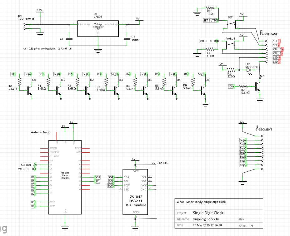
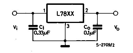
We wanted to run the 12v LEDs and the Arduino from the same power source, so we decided to incorporate a voltage convertor into the board. We chose the L7808 simply because that's what we had lying around. The 7808 reduces the 12v input to 8v output - which is just right to feed into the Vin of the Arduino Nano. We added stabilising capacitors as suggested in the data sheet.
Real Time Clock
In connection with the DS3231 RTC, we learned from a mistake in a previous board. First, you'll see we've used an RTC module - again, because that's what we had lying around. It's not particularly PCB-friendly but it'll do for our needs.
If you use this RTC module, it's important that the battery be accessible for replacement so the header positioning is very important. In fact, when planning the board, the RTC is actually positioned on the underside - but soldered on the upper side. This ensures that the battery is facing out. A disadvantage of this is that the LED is facing down - but more significantly, it's probably not possible to use the DS3231s built-in temperature sensor because it's likely picking up heat from the rest of the board.
In case we didn't want to attach buttons to the board itself, Allan incorporated a header (J2) from which wires can be attached to remote buttons.
A pair of pull-up resistors for the switches are hidden under the RTC in the picture of the populated board below.
The out-of-focus silver-finned artefact at the top is a heat sink to help the voltage regulator.
When I solder such boards, I always take time to make them as neat as I can, lining up the components, making sure they are even and flush with the PCB.
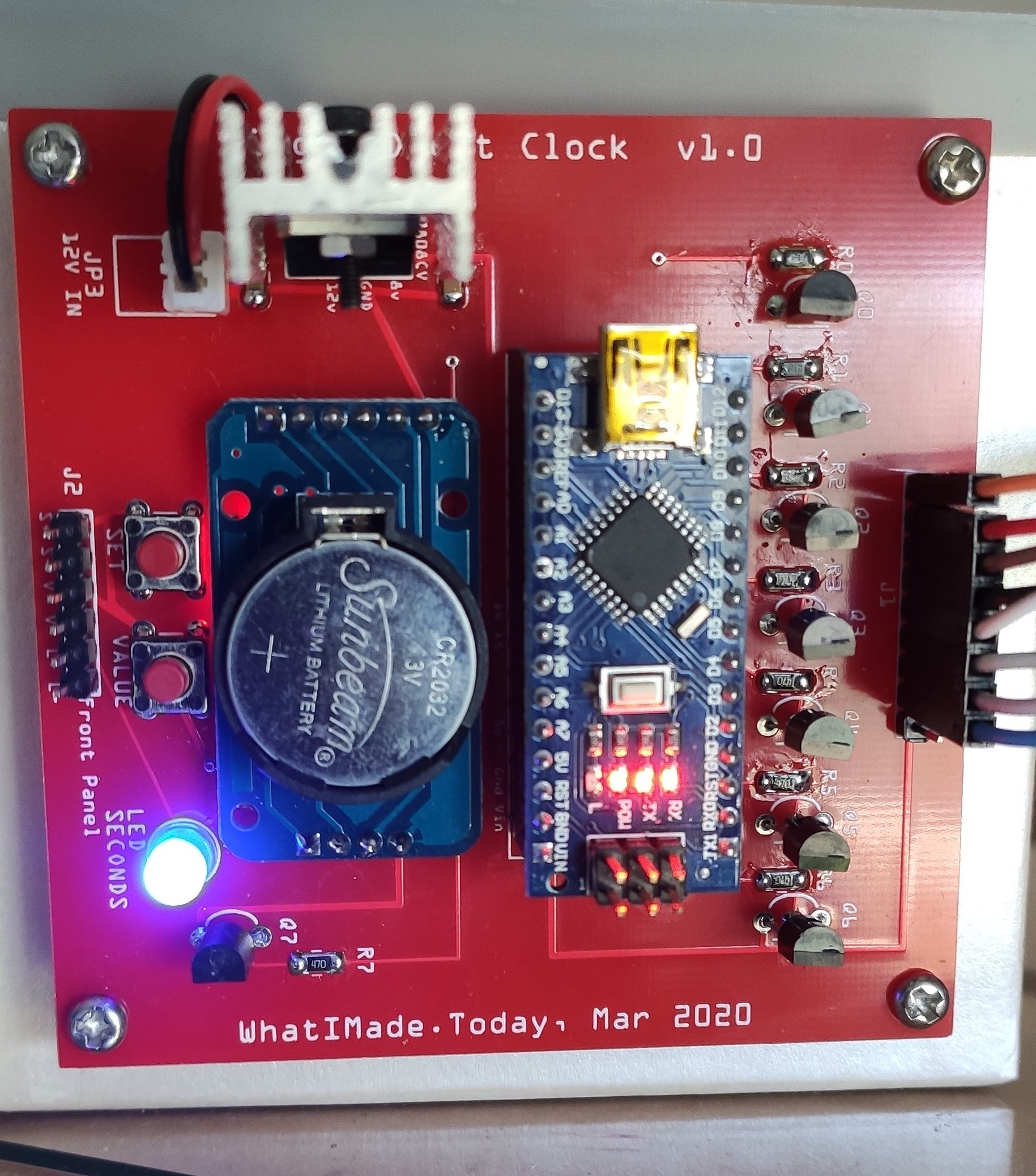
I liked the populated board so much I decided it needed to be displayed along with the rest of the project. So, instead of putting it inside the box, I attached it to the front. The blue LED flashes the seconds to add to the atmosphere.
Setting the Time
When I viewed Mirka's original video I didn't fully understand how he set the time on the RTC. Mirka used toggle switches that made it a little difficult to follow. However, I quickly discovered that it's a simple process and push-button momentary switches make it very easy. To my delight, after I'd set the time, long disconnects from the power source are no problem. The RTC works beautifully and retains the time for instant display.
Printing Different Colours
The clock has been running for a couple of weeks and I really, really love the display. I made a couple of versions with different colours. One of them has dark blue digits which cut the light considerably and make the clock suitable for the bedside.
Get the files
Mirko's files (Arduino sketch, circuit diagram, 3D STL files) can be found here.
Our files for manufacturing the PCB can be found here. (Co-blogger Allan is considering adding a new version of the PCB that uses a single chip in place of the eight transistors and their resistors. He may also re-write Mirko's code to make it simpler for the non-programmer to understand.)