Couple of years back, I've bought an automatic watering system, to water my plants on the window (back then, we lived on 3rd floor).
At first It was nice, and finally the plants stayed alive.
But as time passed, I've noticed that the watering system sipping couple of AA batteries, every 4 weeks.
It was very annoying. But I did nothing about this, because of the common man, I'll buy more batteries tomorrow thoughts.
Luckily (or is it sadly?, I cant tell anymore), I'm at home, with spare time due to the corona-virus epidemic. So it seems like a good time to step up, and do something useful for once!.
So I rubbed some parts from the drawer, looking for interesting (and, obviously cool) things to stuck inside this watering system.
Here's what I found:
- ESP32 X 1
- Rotary encoder(without breakout) X 2
- NeoPixle ring X 1
I think its enough parts, for making something cool.
(If you are a boring person, who's got no spark in his soul you can skip straight to code breakdown)
Otherwise, we can begin.
First of all, some messing around
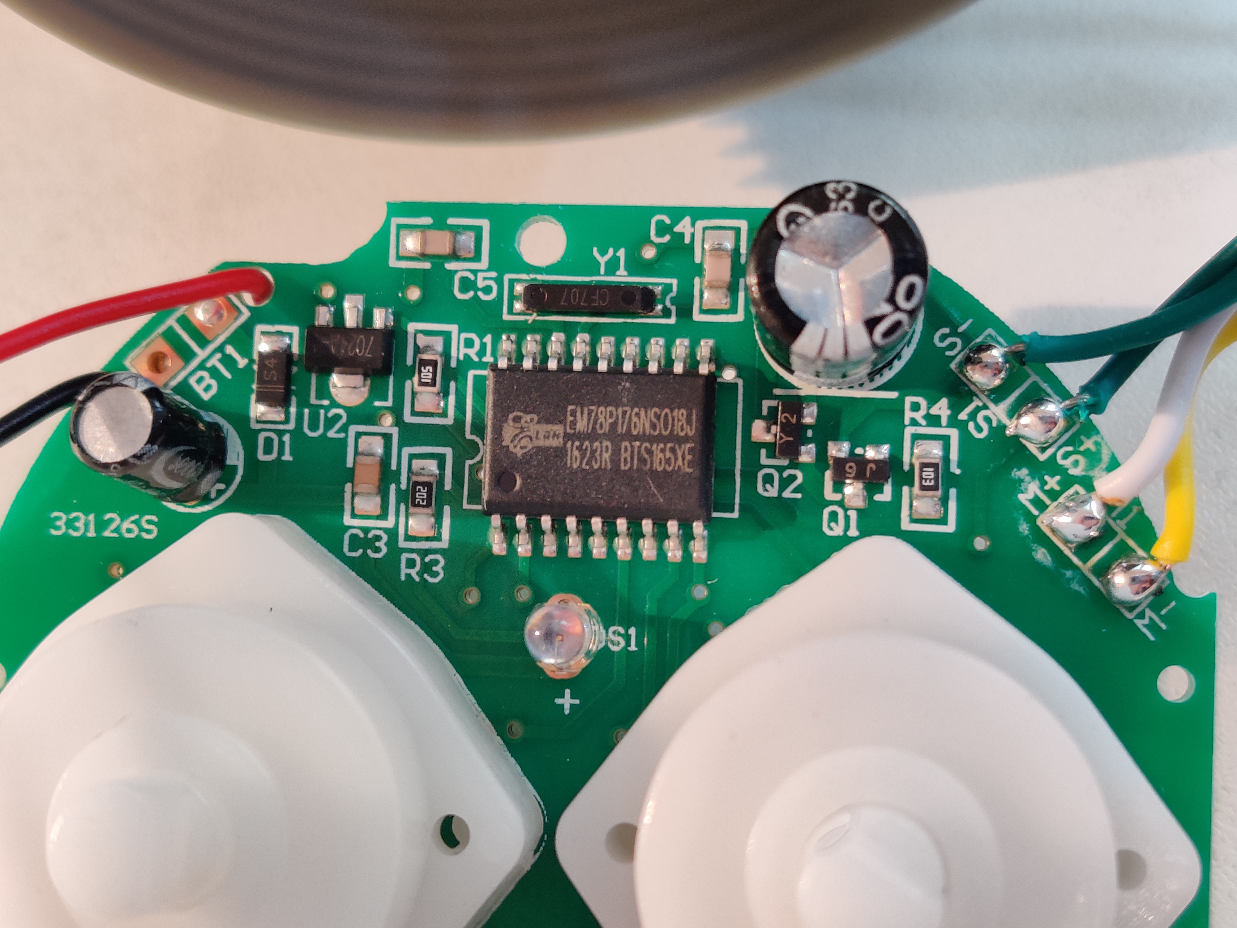
I've tinkered with the old watering system, and in there I found some nice things, that'll make my life easier.
Inside the watering system I've found an electric switch;
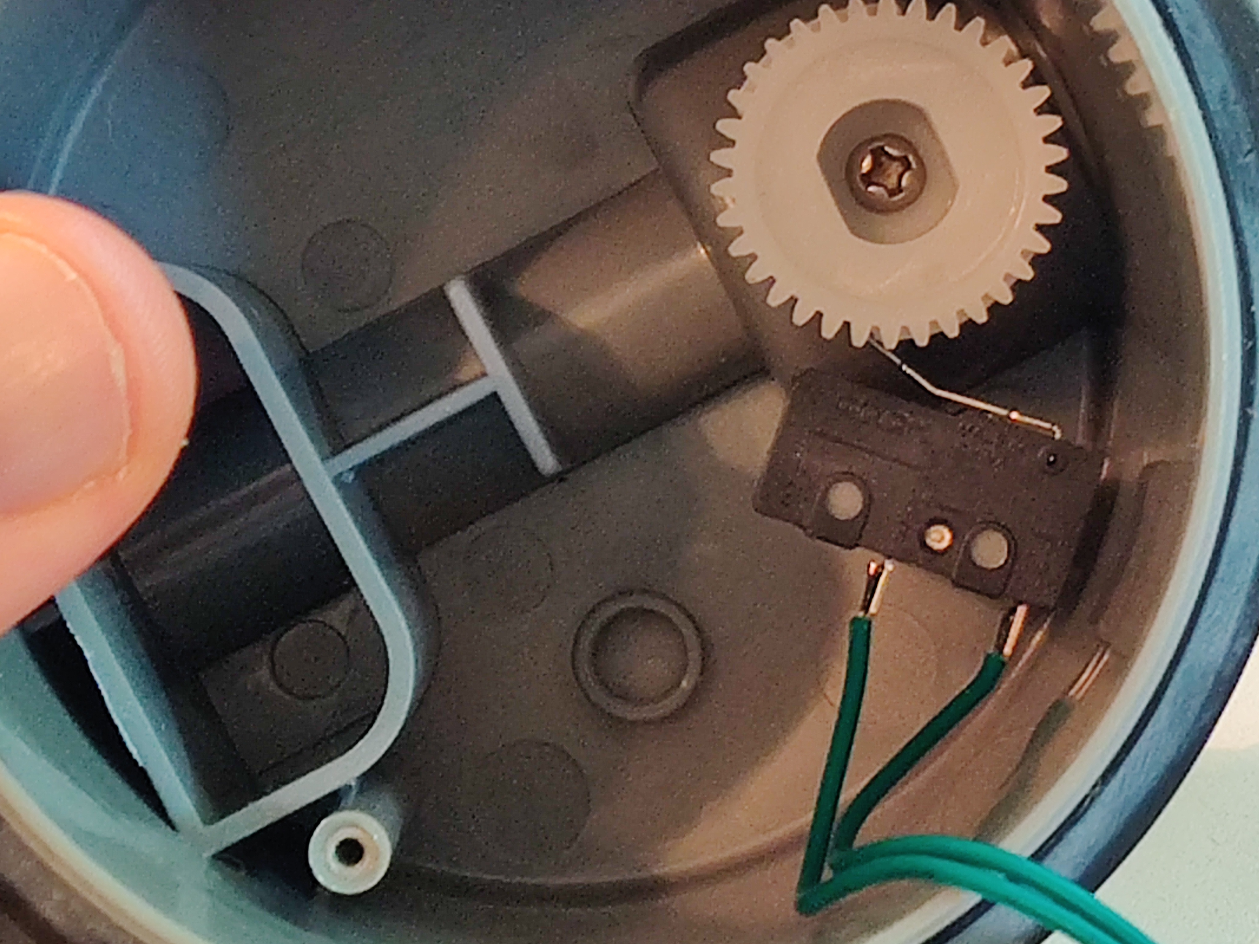
Notifying the systems chip when to stop rotating the motor. It'll make my life easier than tracking valves position.
I've also found that the Valve can rotate 360*, making it easier to hack it, (There's an explain a bit further).
Step 1, preparation
I worked on a fresh Ubuntu 19.10, so did some re-installing.
- Arduino installed from here.
- ESP32 support installed into the Arduino, from here.
2.2. I Checked If everything Is working, using the wifiScan tutorial from the esp32 examples. I did run into 2 problems:
2.2.1. Received an**ImportError** no module named 'serial'. Solved that withpip install pyserial.
2.2.2. Got anarduino [Errno 13] Permission denied: '/dev/ttyUSB0'. Solved that bysudo chmod a+rw /dev/ttyUSB0. - Setting Over-The-Air (OTA), using the OTAWebUpdater from Arduino examples. Thus enabling me to update ESP32 code Over-The_air.
Now that we have Arduino installed, and fully operational ESP32, that can be updated over the air, we can continue.
Step 2, figuring out things
Inside the automatic watering system there's an DC motor, rotating a valve.
I want to use the same motor, to rotate the same valve.
Thing is, to work with a DC motor, one need a DC driver, which I don't have.
So I thought to connect the ESP32 to the watering system on-board DC driver, which I don't see.
So I consulted with my MAKER friends (also authors in this glorious blog), and they suggested to use MOSFET, which I don't know what It is.
It sounds like the beginning of a joke, or a great post.
I'll let you decide.
Before diving into learning new things,
I need to check if the motor can be operated on 3.3V.
So I've connected it directly to the ESP32 3.3v output, and voia!
Luckily, it does, now we can go deeper.
A motor driver?, really?
Here is an example of one (the L298N):
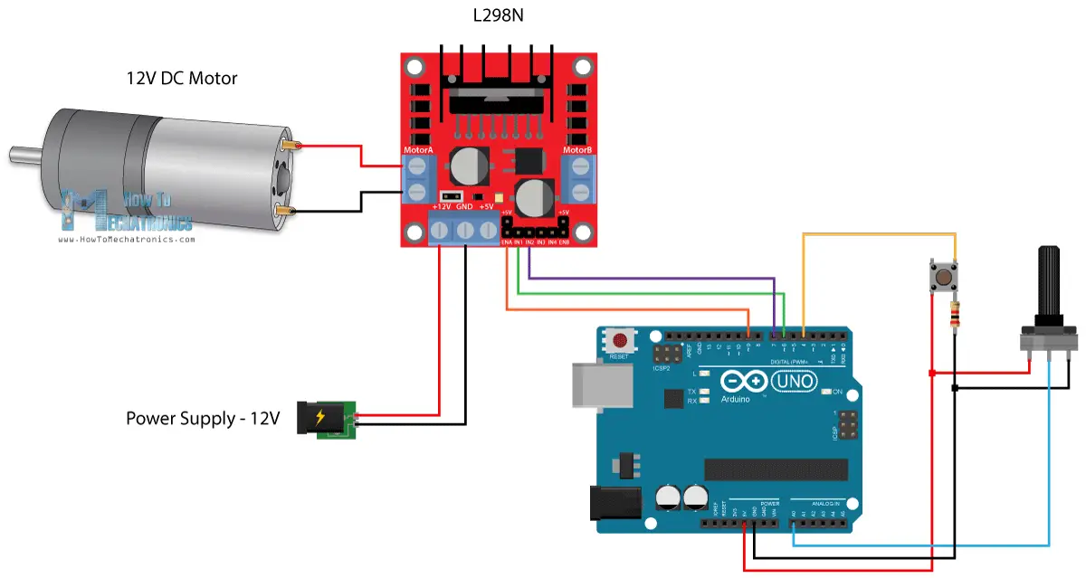
Thing is, DC motors run in various voltages, while the control is usually in 3.3v,5v,12v. So how one give commands using 3.3v to a motor that work on 60v? That's right - Using a driver.
One more thing about the DC driver - it can change the direction of the motor, all one needs to do, is to give the right command.
Luckily, inside my automatic watering system, the valve can rotate 360, so no need for the *bidirectional rotation feature. I do need to control the motor though (e.g start & stop).
Iv'e tried to connect the + of the motor to a GPIO pin, and the - to ground, then set this pin to HIGH in the Arduino. Nothing happen, but that was obvious, right? because we all know that the ESP32 GPIO pins can draw as much as 12mA, which is no good for rotating a DC motor.
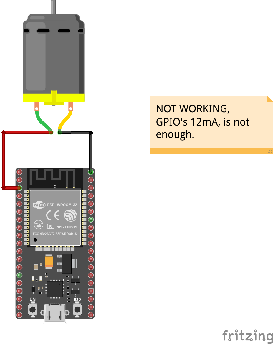
So, I need to operate a DC motor, using a 12mA current?
Directly - that's not possible.
I need some 'thing' that the GPIO pin controls, and in response, that 'thing' controls the DC motor.
- At first I thought to use a RELAY, something like that:
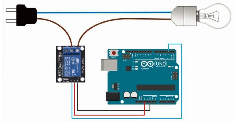 Although a relay use 3.3v to operate things that require much more voltage, I is a binary switch, there's ON state and OFF state.
But what if I want to use some analog input/output that comes from much higher voltage than the GPIO can work with?
Here comes the MOSFET..
So, what is MOSFET?
A metal–oxide–semiconductor field-effect transistor,
also known as the metal–oxide–silicon transistor (MOS transistor, or MOS), is a type of insulated-gate field-effect transistor (IGFET) that is fabricated by the controlled oxidation of a semiconductor, typically silicon.
The voltage of the covered gate determines the electrical conductivity of the device; this ability to change conductivity with the amount of applied voltage can be used for amplifying or switching electronic signals.
The MOSFET is the basic building block of modern electronics, and the most frequently manufactured device in history, with an estimated total of 13 sextillion (1.3 × 10²²) MOSFETs manufactured between 1960 and 2018, wikipedia.
Simply put,
Its a transistor, that change its conductivity, given some voltage.
Using this MOSFET, I could operate a 5V DC motor using the Arduino 3.3v gpio.
Nice. Right?
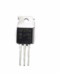
A MOSFET, TADA!

A working example, using a mosfet:
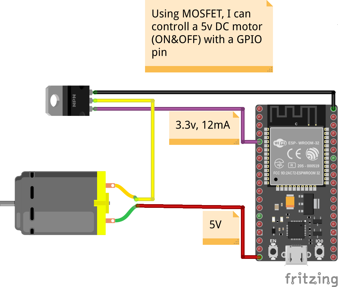
And a working proof:
I've set the GPIO pin to LOW, and the conductivity changed accordingly
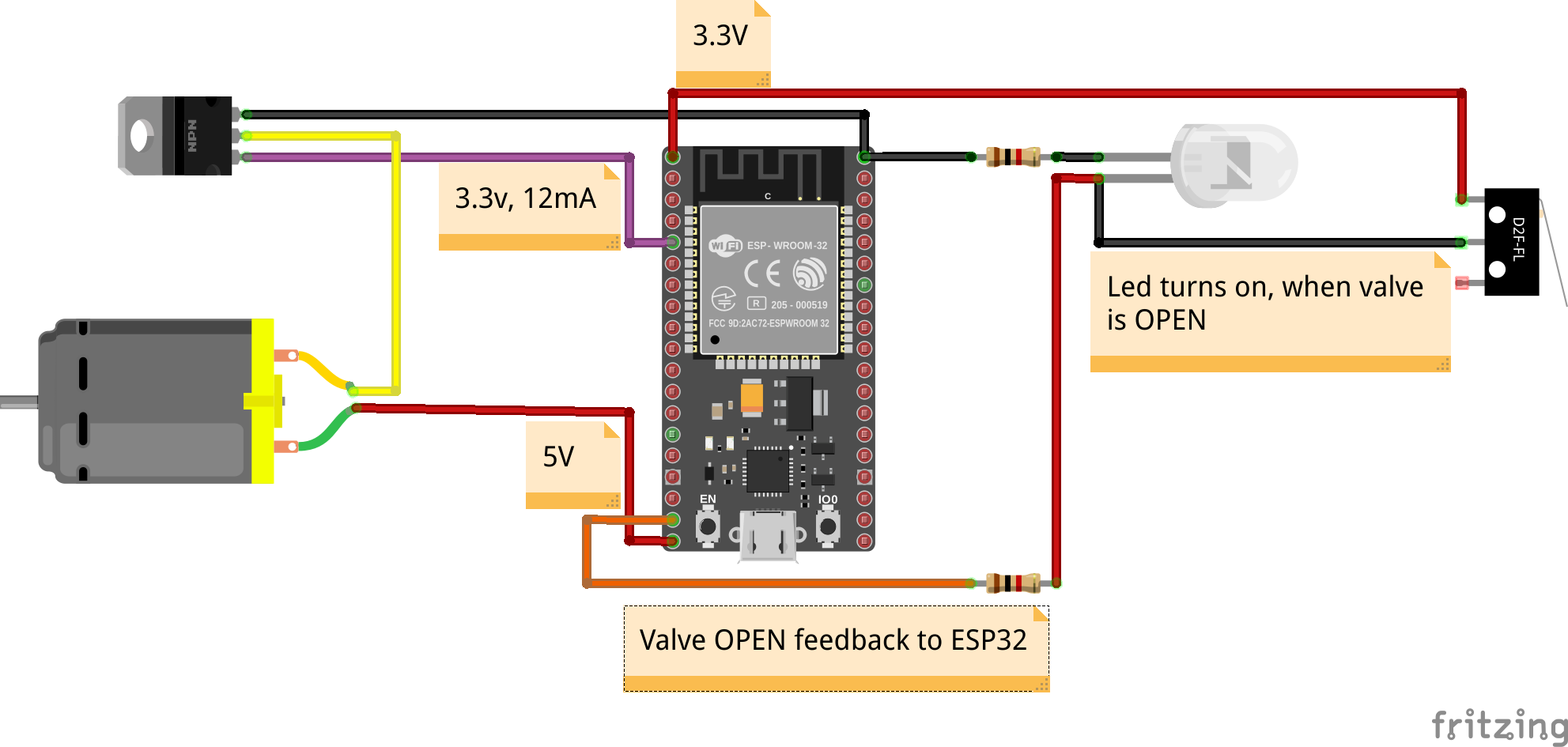
Knowing valve's position
Earlier, I've mentioned that there's a micro-switch, giving feedback about the valves location (mainly OPEN/CLOSE status).
Here how I have used it in my favor:
Finally, I done with all the electronics. Time to write some code :)
Step 3, Adding functionality
We saw in the original plastic cover, that there are 2 rotating switches:
- RUN TIME
- FREQUENCY
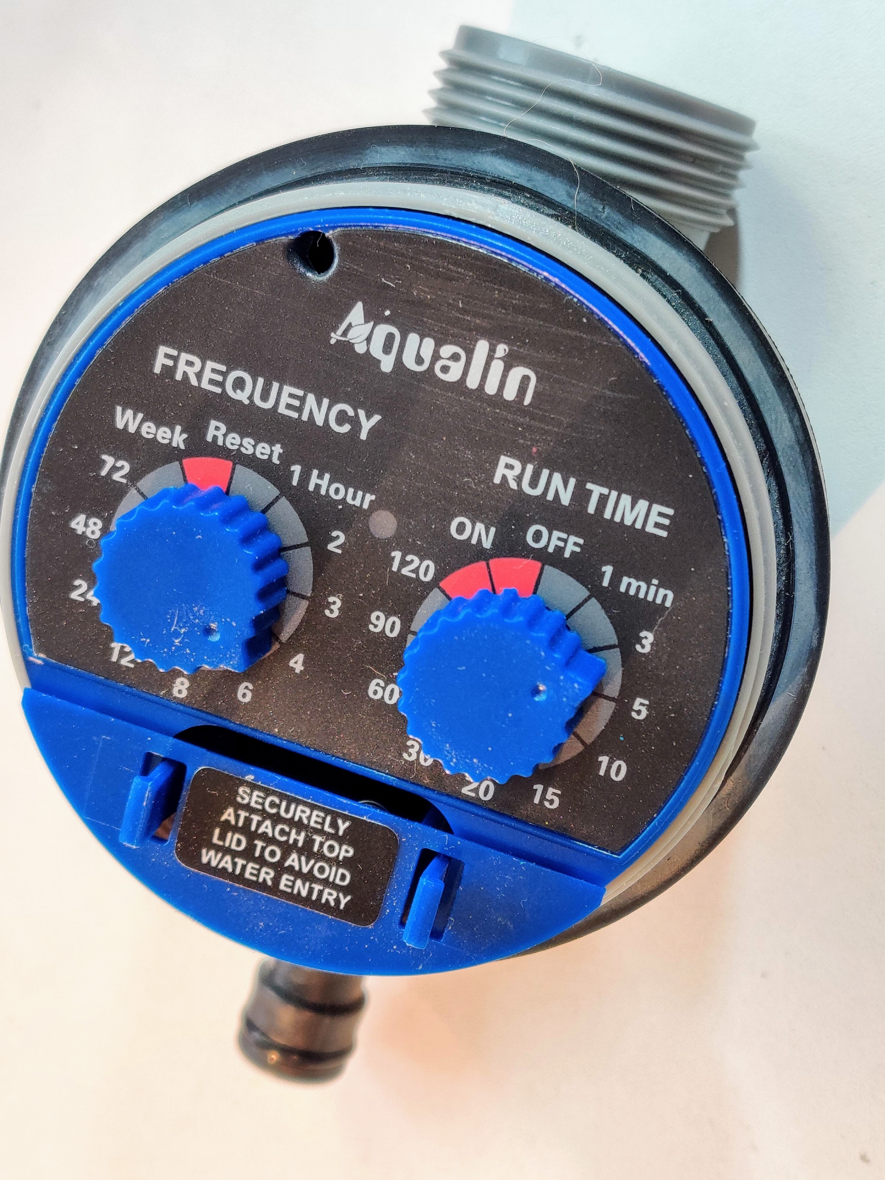
I kept these functionalities, just moved them from physical switch, to the cyberspace (wooo buzz word!):
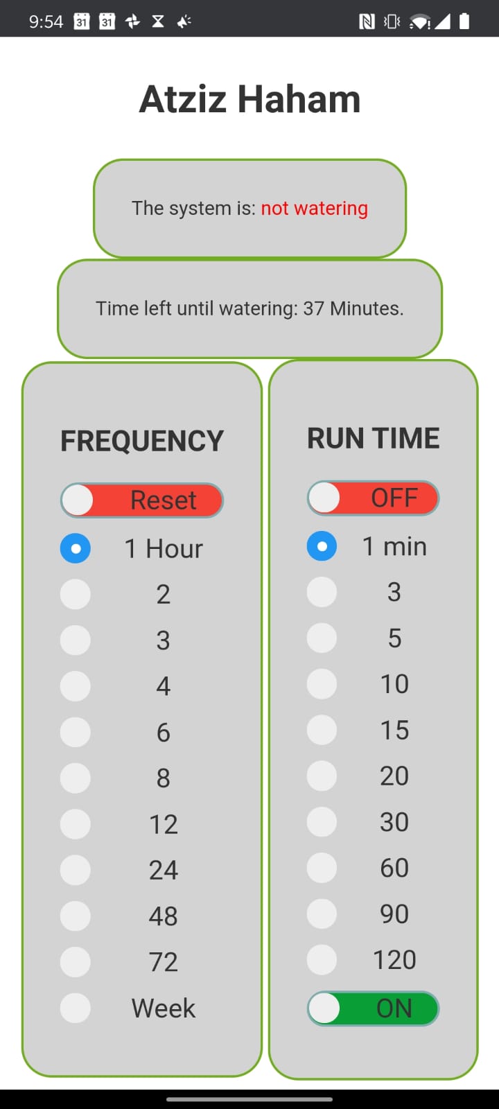
(Atziz Haham, meaning smart plant in Hebrew.)
Lets break the code
While this is not my first rodeo with ESP32 and an HTML web-server (I also made the BabySleeper), I did learned a lot!
Lets break the code with a BOTTOM-TOP approach:
Its the projects architecture, to be able to water the plants for curtain amount of time, in intervals of some hours. That sound classic for the Arduiono's loop() function right?
Implementation could be something like that:
void water_the_plants(int runtime_duration){
    openValve();
    delay(runtime_duration);
    closeValve();
}

void loop(){ // Run indefinitely
    water_the_plants(runtime_duration);
    delay(frequency_duration);
}
But its problematic, say I want to change runtime from 1 minute to 3, while the system is watering the plants. By default water_the_plants() is non interaptable, It should water the plants as much time as it needs.
So what?! If the system is watering the plants, it is non responsive for user input?!
That is a big NO NO in software design terms
It seems like water_the_plants(int runtime_duration) should run in a separate thread. So the system could water the plants while being responsive to user input.
Hence for the first time (like, EVER), I used Arduino's Tasks.
Its a thread-like mechanism that can run in parallel.
Why thread-like?
By definition, a thread is not something that can be killed from the outside, for example:
void my_thread(){
    while(1){
        do_stuff;
    }
}

void setup(){
   thread *t = thread(my_thread);
   t.start(); // that's OK
   delay(1000);
   t.stop();  // NO SUCH THING IN A THREAD!
}
If a program needs to do something after a thread is done, it needs to t.join() meaning:
Ill sit here, and wait until you do you.
Meanwhile, Arduino's Task can do exactly that!:
BaseType_t xReturned;
TaskHandle_t xHandle = NULL;

xReturned = xTaskCreate(
              runtimeTask,        // Function that should be called
              "Watering task",    // Name of the task (for debugging)
              1000,               // Stack size (bytes)
              NULL,               // Parameter to pass
              1,                  // Task priority
              &xHandle   // Task handle
          );

// Kill runtimeTask if it's running
if( xReturned == pdPASS) {  // If the task was created successfully then pdPASS is returned.
    vTaskDelete(xHandle); // KILL THE TASK FROM OUTSIDE OF IT!
}
That was a brief intro to threading and Arduino's task's
Now, we can continue with designing thoughts.
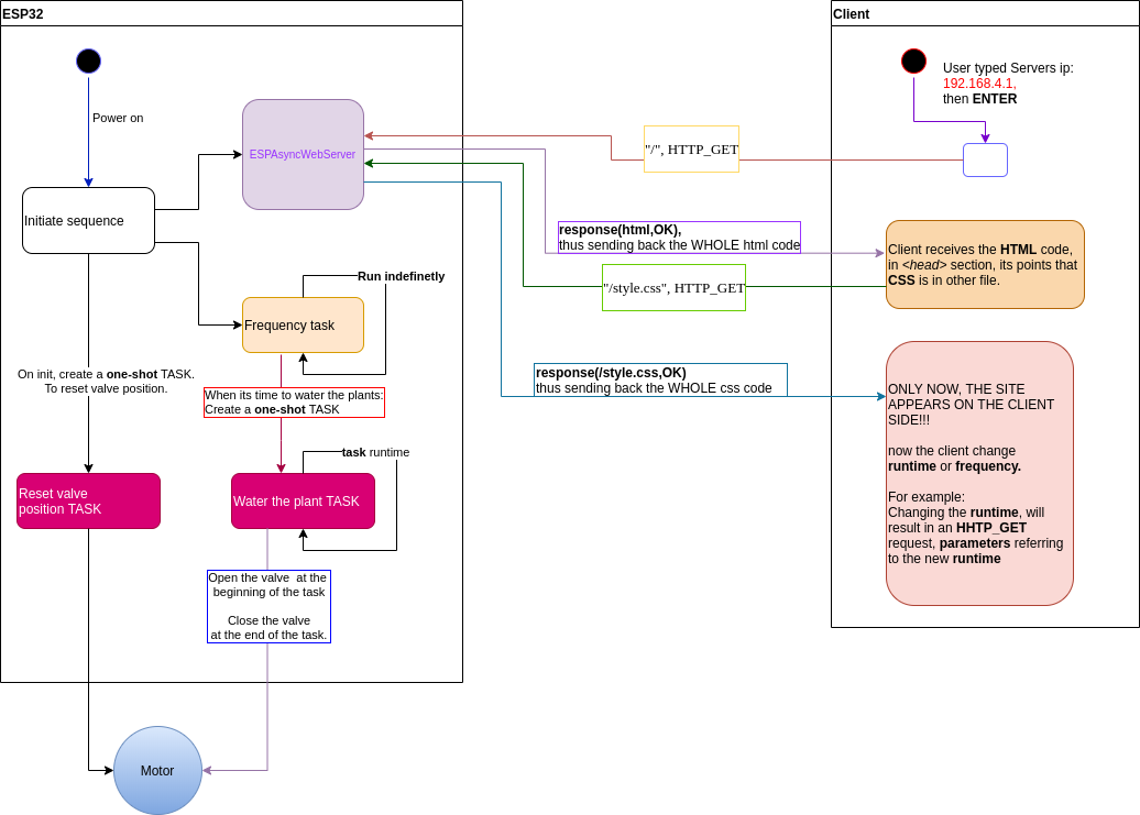
- I want to have a server running on the Arduino, this server will do the following:
- Send the clients valve status (open/close), and time left until next watering.
- Receive from client RUNTIME & FREQUENCY requests.
This server should also run in parallel to the watering function. Luckily, there's an ESPAsyncWebServer, that do exactly that.
Here is how I used it:
The server work on "HTTP-GET" requests, that are being sent from the client to the server, with the url telling from where the client sent the "HTTP-GET".
For example:
  server.on("/", HTTP_GET, [](AsyncWebServerRequest * request) {
    request->send(SPIFFS, "/index.html", String(), false);
  });
This line tells the server that when it receives a HTTP-GET command, from the url "/", then it sends back (request->send()) the SPIFFS (that contains the html itself).
So in order to send the clients valve status (open/close), and time left until next watering:
server.on("/isSystemWatering", HTTP_GET, [](AsyncWebServerRequest *request){
    request->send_P(200, "text/plain", String(isSystemWatering).c_str());
  });

server.on("/getTimeLeft", HTTP_GET, [](AsyncWebServerRequest *request){
    request->send_P(200, "text/plain", String(time_left_until_next_watering_min).c_str());
});
All the above was server side.
How does it look like in the client side?
An html skeleton should look like that:
<html>
<head>
    // Site graphics declarations (i.e fonts, colors, libraries etc)
    some-definition
    some-more-definition
    some-css-declarations (can be in a separate CSS file)
</head>

<body>
    // How the site will look (i.e photo locations, paragraphs filled with text etc)
    some-headers
    some-text
    some-photos
    some-paragraphs

    // Another example of things inside the BODY:
    <div class="note">
        <div class="data">
            <a> The system is: </a><a id="isSystemWatering"></a>
        </div>
    </div>

</body>

<script>
    // Sites logic (i.e function that responds to a pressed button by the user)
    function isSystemWatering( ) {
    }
</script>
</html>
In the client's htmls body section there's this line:
<div class="note">
    <div class="data">
        <a> The system is: </a><a id="isSystemWatering"></a>
    </div>
</div>
And in the script section there's a function:
function isSystemWatering( ) {
  var xhttp = new XMLHttpRequest();
  xhttp.onreadystatechange = function() {
    if (this.readyState == 4 && this.status == 200) {
      if (this.responseText == 0){
        document.getElementById("isSystemWatering").innerHTML = "not watering";
        document.getElementById('isSystemWatering').style.color = "red";
      }
      else{
       document.getElementById("isSystemWatering").innerHTML =  "watering";
       document.getElementById('isSystemWatering').style.color = "blue";
      }
    }
  };
  xhttp.open("GET", "/isSystemWatering", true);
  xhttp.send();
}
Break down:
- At first, a new
XMLHttpRequest()is created. - Then I attached a function that will be called when the server responds:
xhttp.onreadystatechange. - The attached function will do the follow:
- Check if the server respond with "OK" (200):
if (this.readyState == 4 && this.status == 200). - If it does: update the clients html, where there's an element with an
id="isSystemWatering", with the corresponding text.
- Check if the server respond with "OK" (200):
- Finally I will open a "GET" request, with the
url = /isSystemWatering. - And send the request to the server.
The logic is being reused for other purposes, but the main idea is the same.
This is how I implemented all the functionality of the server.
And last but not least (as promised, a BOTTOM-UP approach):
Project's high level overview:
Project summary
I love messing with Arduino.
At the beginning, it was all about toggling a LED on & off,
later on, I used Arduino to read sensors (gas, temperature & humidity sensors),
then I used the ESP32 (also, Arduino) as a server.
Today I've learned all about Tasks.
It seems that every time I mess with Arduino, I get closer to the bare metal of things.
And I love it!
Cheers, Gal
Code n' stuff - my github