This is a following post to I'm Talking on Sunshine - Part 1, where the goal was to build a solar-powered station for charging many cell phones - the result was of course awesome!!
After describing how to build a solar panel on my first post, I'll explain about the rest of the construction.
Basic Electronics Needed
On this section I'll describe the minimum needed in order to have a stable phone charging station, the other sections will be bonus for whoever choose to keep reading.
The idea is to use the energy coming from the solar panel in order to charge a battery, and use the battery to charge the phone. That way your station will work all day and all night and will be less dependent on the sun. Here's a photo of the basic circuit used in the process, followed by detailed description of each part:
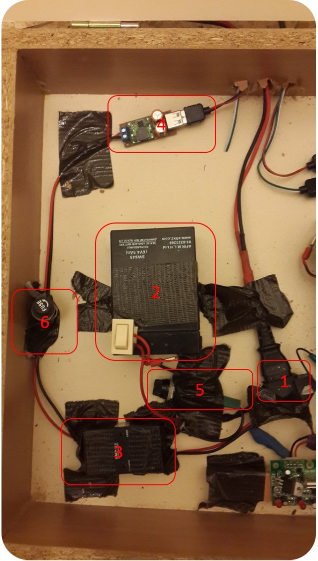
Connection from the solar panel - After building the solar panel you'll have positive and negative wires coming out of it, make sure you know which belongs to which. It is also recommended to connect a Schottkey diode in series to one of the wires, one which can hold the maximum current the panel can produce. In my panel, I had 24 cells of 0.5V/4A in series, which means I needed a diode which suits to 12V/4A circuit. Also, make sure the wires are thick enough to hold the high current. In the picture you should notice the thick wires and the "monitor power" connector I've used so it can be unplugged easily.
Lead-Acid battery - These batteries are big and heavy, but strong and easy to charge. In the picture there's a 6V battery 4.5AH. For more information on the term "AH" you can read my post on batteries. A 6V lead-acid battery needs about 7.5V from an external source in order to be charged (The current will then flow into the battery and not out of it). These batteries usually come in values of 6V,12V,18V etc. If you intend to use a battery of 12V you should note that the voltage needed to charge it will be about 14.5-15V. In my project the solar panel did not produce more than 12V, therefore I've used the 6V battery. It'll be a good idea to add a switch as well, so you can turn on and off the battery power whenever you like and do not need to connect/disconnect any wires.
Charge Controller - This item can actually be quite expensive, but also can be found as cheap as in the added link. At first I thought about building this circuit on my own, but soon enough I found out it is a bit complicated for my level so I bought one. The charge controller has three connections: To the solar panel, to the battery and to the rest of the circuit. With these three connections it solves a few problems at once:
a. The voltage from the solar panel is unstable, on my project it can be changed from zero to 12V depends on the sun angle, shadows etc. As long as the voltage is high enough, the circuit step-down the voltage to stabled 7.5V on the battery connection and 6V on the third connection in order to power the rest of the circuit.
b. The third connection will get 6V, either from the battery or the solar panel. If the battery is disconnected the energy will flow from the panel, if the panel is disconnected the energy will flow from the battery. When both connected the charge controller will make sure the
circuit gets 6V and if possible - the battery gets 7.5V and being charged.6V to 5V step-down module - In order to charge your phone you will need voltage of 5V. As long as your battery does not produce exactly 5V it is best to use a step-down module to get a stabled 5V voltage. In the link I've added, and also in the picture, the step-down module already has a USB female connector which can save some time and soldering but not necessary. Notice this module can get an input of 6V-35V and give output of 5V where some other step-down modules can get minimum of 7V and therefore will not work with a battery of 6V.
20A fuse - The fuse is connected in series straight after the battery output. Lead acid batteries have the ability to produce high currents in short times (This is why they are used as car batteries - they have the power to start a car engine). Therefore, if by any chance the circuit around the battery will get shorted, the amperage can be so high it will start a fire (I actually tried it by mistake... Do not try this!). On a normal use the amperage will not go higher than 20A so a fuse which will cut the circuit in case more than 20A will flow is very reasonable.
3A fuse - The step down modules usually have a maximum current allowed, mine is 3A. When exceeded the module can be burned and not work anymore. If you intend to use this module to charge several phones or a big tablet you might actually need more than 3A. It is recommended of course not to connect any products which will need more than 3A but if you go public with this project you can't predict what people connect to the charger, or if they damage it and short it by mistake. Therefore a 3A fuse is recommended to be connected in series before the step-down module.
Connecting all the above will give you a stable charging station. From here you can split some wires from the output of the step-down module and build as many chargers you wish. I had two charge controllers and two 6V lead-acid batteries, one of 4.5AH and one of 12AH so I built two stations as described above, notice the bigger battery has two step-down modules - this has made just to divide the power from the battery to more chargers.
My plan was to build nine charge stations and these two batteries were way more than what I needed. 12Ah battery means it can charge 12 phones at a current of 1A for one hour, even when there isn't any sun to charge it at the same time. That is quite a lot! But yet I've decided to use both batteries for backup since I didn't know the health conditions of any of the batteries. However, knowing that through the night the battery will probably last has eventually contribute to some more cool features for the station, such as decorative lights.
Building the Station
On this section I'll describe how I've built my own station. After completing the basic electronics from the previous section, everything described here will be nice-to-have tips to make the station more cool, practical and easy to handle.
Monitor, Wood and bottles - The Box
When I just finished building the solar panel, the one described on my first post, I had only one week until the festival, the same festival I waned to bring my project to. With the help of Notamacuser we constructed the phone charging station with whatever we found. We needed a box to put all the electronics in, so we found an old CRT monitor and took everything out except the plastic cover. That way all the electronics could be nicely arranged inside, and each battery produced energy to 4 chargers.
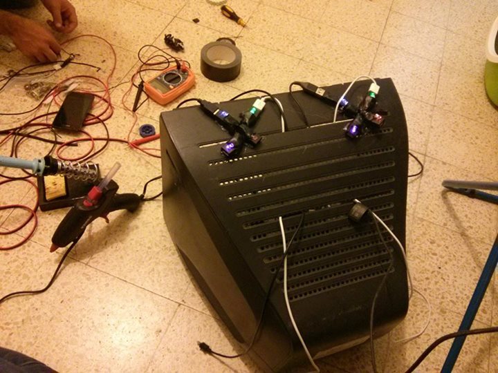 From each step-down module I splitted 4 USB connectors, which were glued to the monitor with hot glue, and the front of the monitor was covered with an old T-shirt to hide the electronics and to make it easy for maintenance.
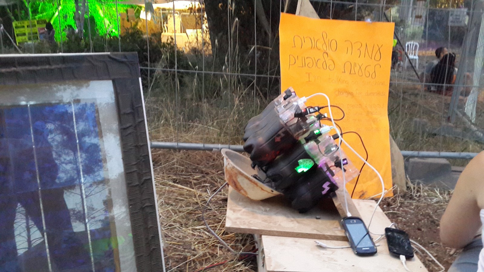
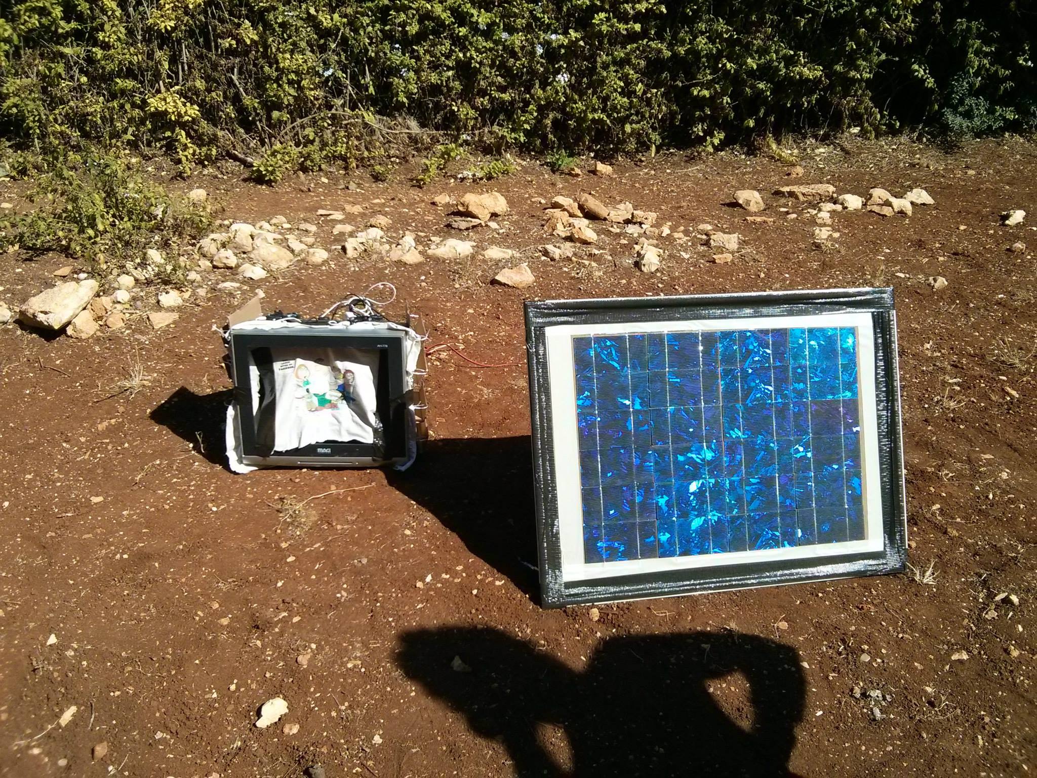
 This is how it looks like - this was the first time I took it to my garden and it actually worked with the sun power!
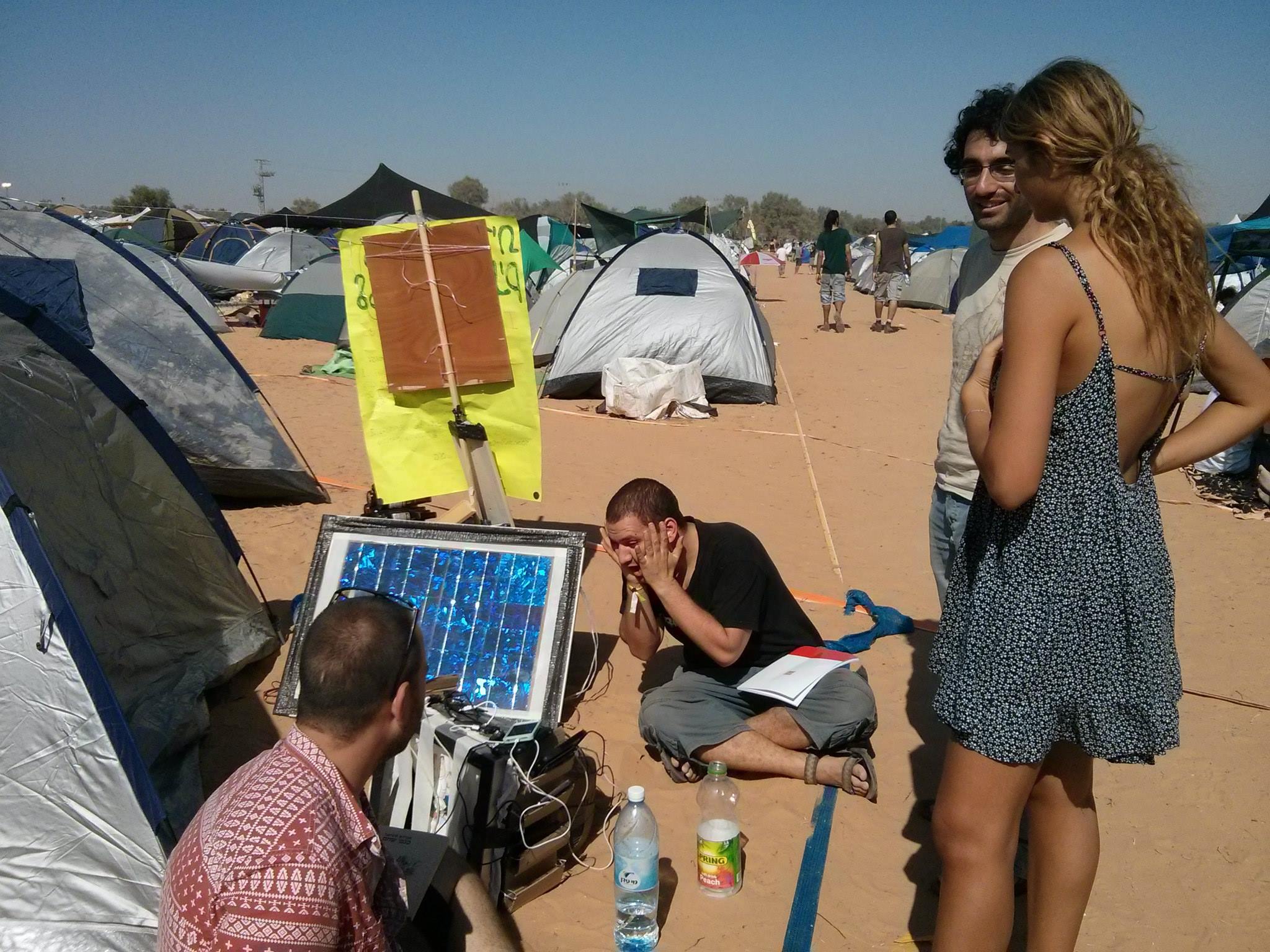
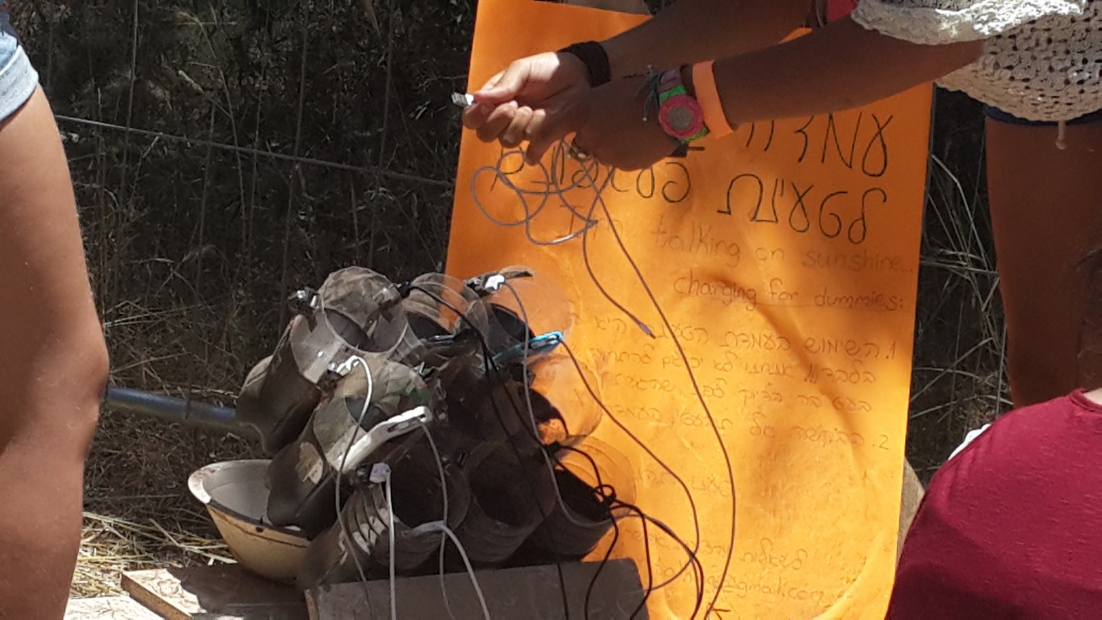
 On the sides of the monitor we added some cardboard to put the phones in while charging. Here is how it looks like when someone was really excited about the station in the festival:
So, this was version 1.0 of the the solar station, and it had a few flaws which should have been taken care of:
1. The monitor was much bigger than needed for all the electronics, and was not so convenient to handle.
2. The festival was in the desert, with a lot of sun, which was good for the solar panel but not so good for the hot glue. Wherever the hot glue was directly exposed to the sun it melted a bit, and the USB connectors were loose.
3. The cardboards didn't hold the phones so well, some were torn during the festival.
4. Some connectors broke, people looked inside the monitor to try and fix it and of course it didn't help.
The big advantage of the station was the panel and the concept. The panel actually worked and provided energy for 3 days, and the rest was now ready to be upgraded for the next festival.
Version 2.0 of the solar charging station had two parts, the hidden electronics box (on the right) and the visual apparatus for holding the phones (on the left):
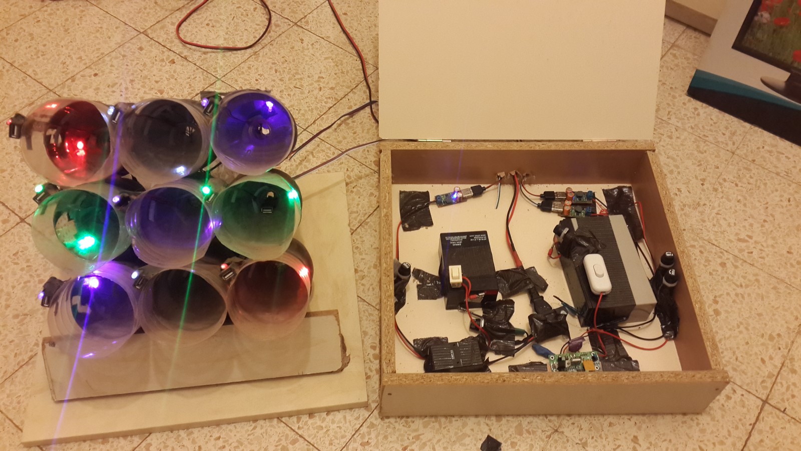
The box was made by several particleboards and a jigsaw. Two parts of the same size, for the floor and the cover, and four other pieces for the box walls. This way, the box size was perfect to hold all the products. At the back of the box I've added two hinges so the cover could be opened and closed easily, and drilled three holes for the cables.
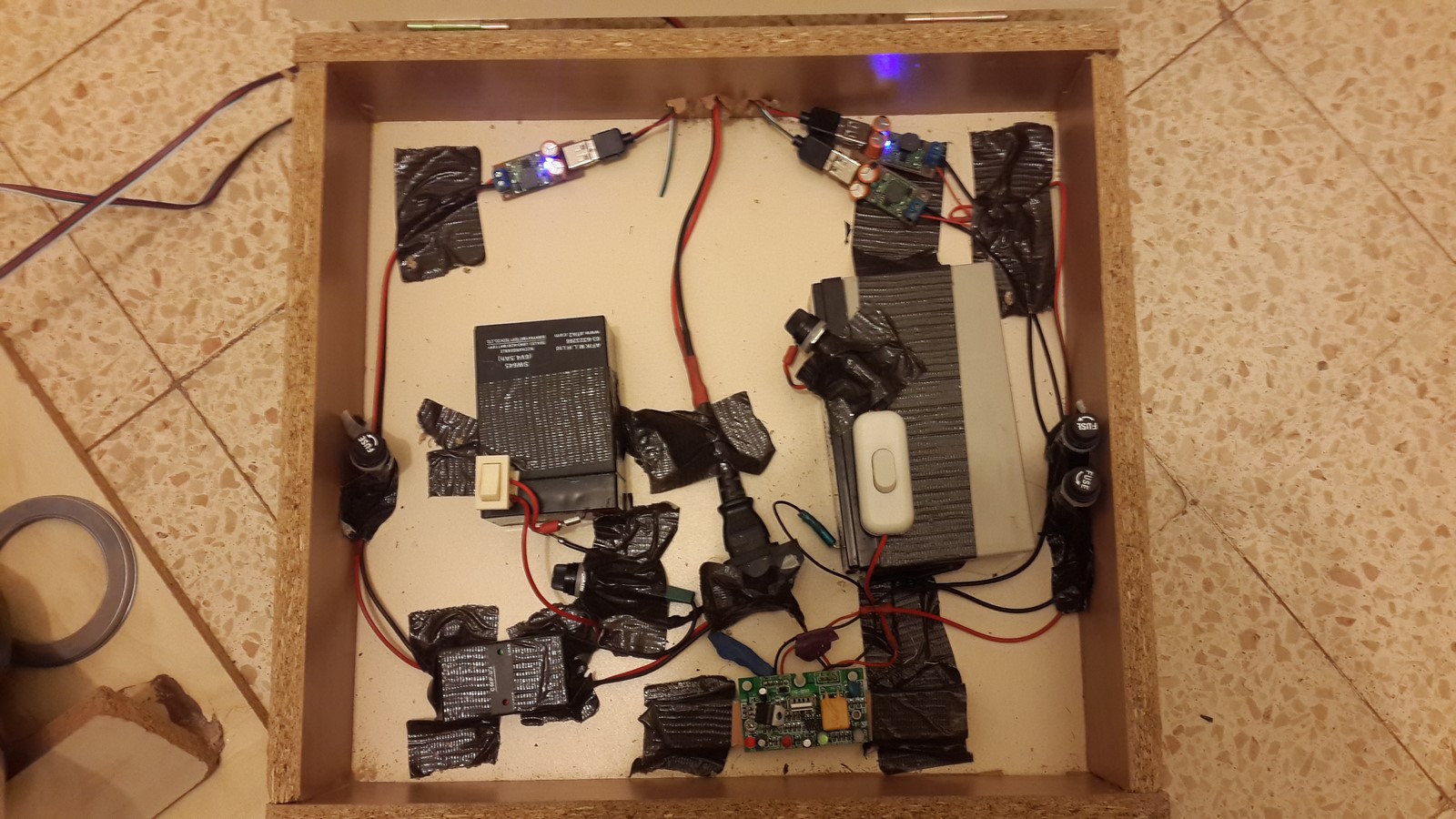
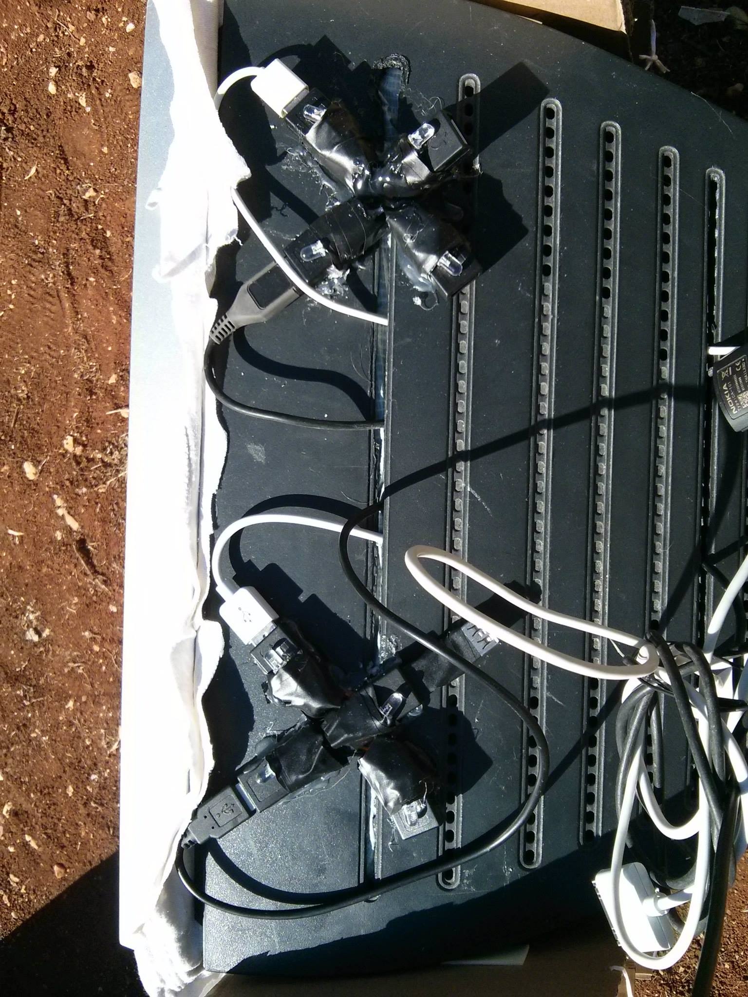
 The electronic parts were arranged inside the box, as seen in the pictures at the first section. I was mostly afraid that some items will move and touch other items causing a short-circuit so I've used a lot of gaffing tape to hold everything, and made sure each part has its place, with enough space from other parts.
In order to make the second part of the station, nine 1.5 litre were used as nine phone holders. Each bottle was cut in half, and the bottom parts of the bottles were painted and glued together to a 3X3 matrix. Any adhesive will be good enough to glue the bottles and if you want to be creative you can paint them however you like, or as I did - put some shaped gaffing tape, spray and remove the tape and you will get your shape.
The next step was drilling holes at the back of the bottles (can be done also before glueing them together) so the wires can be inserted through later on. In my case, I have also used the top parts of the bottles by simply inserting them into the bottom parts. By using the top parts, you'll be getting a bit wider area to put the phones in but also an isolated area so the phones will not touch any wires since the wiring itself will take place between the two parts of the bottles. This is how it looks eventually from above:
USB wiring
After completing to construct the basics form the first section of this post, you already have a power source of 5V and all needed to be done is to split the power source to many USB female connector as you want. The USB connector has four pins but only two are needed to supply charging to your phone - "5V" and "Ground". However, the two other pins needed to be connected to each other as well and some resistors might be needed to be added between those pins and the first two pins. I recommend to read my post on USB chargers in order to get this part work in an optimal way. If the connection are not well-soldered or the wires are not thick enough you might get a very slow charging, if any at all. When describing the step-down module I've mentioned I've used 3 of those, where each can handle up to 3A of current. Now is the time to explain my choices - I've figured out that each charger, when used, will draw 0.5A for a slow charge and an average of 1A for a fast charge. So dividing each row in the 3X3 matrix to one step-down module sounded like a practical solution to make sure none of the 3A fuses will get burnt.
Adding a LED to each connector will be a good idea as well. That way you'll know to spot connection errors very fast. A LED needs a very low amount of current and therefore will almost doesn't have any effect on the battery and the charging status. In order to connect the led, you should first test it by connecting it to a variable resistor in series and then to 5V. Lets say that a led needs $V = 2.4V$ in order to work, and $I = 1mA$ of current will make it bright enough for your needs, then the next step is to calculate what resistor $R$ to use using this simple formula:
$R = \frac{5 - V}{I}$
In our example you'll need a resistor of 2.6KOhm. After soldering the USB female connector you can solder the resistor to the "5V", then the led anode to the resistor and its cathode to the "ground". After completing this part it is easy to identify connection errors by using this method:
- One led is not working - Check the specific connections between the step-down module to the USB connector.
- Three leds are not working - Check the connections between the charge controller and the specific step-down module.
- All leds are not working - Check the connections between the battery, solar panel and the charge controller.
Also, if you have read the post I mentioned, you'll know that in order to fast-charge some of the phones (iPhone, SGS4, Nexus 4) different connections are needed. Using the colored leds you can "mark" the chargers to help the users to know which charger is optimal for certain phones .
Bonus: Semi-Smart Lights
Everything is working and now it's time to add some more lights to the station so when it is dark everyone will know where is the center of attention, especially because we've got a very powerfull battery. Adding more leds in different colors can be done the same way as the connectors leds, but while nine leds which draw 1-5mA are not such a big deal, 30 leds will already have a bit more impact on the battery level and it will be a waste if they work all day when the sun is shining and they can't be seen. Therefore I've created this electronic circle, which will turn the leds only when it is dark enough:
 This is actually a very simple circuit, no micro-controllers needed - only analog parts. The Q1 and Q2 are two NPN transistors (You can find some basic information about transistor on this post , on the "Output" section). The two transistors are connected as a Darlington transistor, which means that when a very small amount of current flows on the orange line and the voltage on R5 is more than ~1.5V, Q1 will be opened and the necessery current will flow through the leds.
On the orange line we have a variable resistor R6 and a photoresistor R5 (LDR). The LDR has low resistance when there is light and high resistance when it's dark. When there's light, the voltage on R5 will be smaller than 1.5V, and both Q2 and Q1 will be closed, meaning the leds will not turn on, hence no energy will be wasted. When it is dark R5 will have higher resistance, followed by higher voltage and even though a very small amount of current will flow through R6 and R5, it'll be enough to make the leds to be as bright as you want. R6 is variable, so you can choose exactly what amount of light will cause the voltage to go higher than ~1.5V. Leds of the same colors can be connected in parallel, together with a variable resistor (R10) to control their brightness. I also added another resistor (R11) so I will not burn the leds by turning R10 to zero resistance by mistake. Leds of different colors have to be connected separately since they need different voltage to be activated.
Sound complicated? Well it is not, eventually it looks like that:
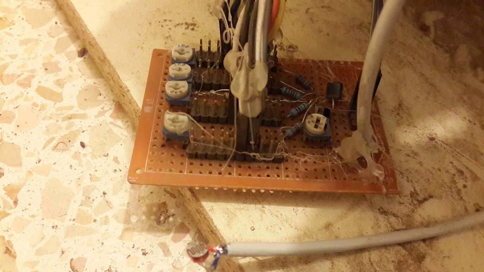 All the pins in each column in the picture are connected in parallel and the leds can simply be connected to the pins, and the LDR is connected with a long gray cable and can be put everywhere you want. The next video shows the circuit in action where all I did is putting the LDR on a working led and take it away from it:
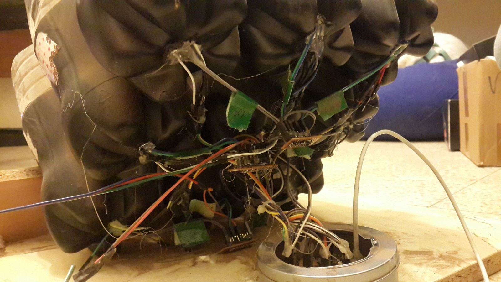
Make sure to arrange all the wires you are using and label them. Using a lot of leds and wires will look like that in the back of the station:
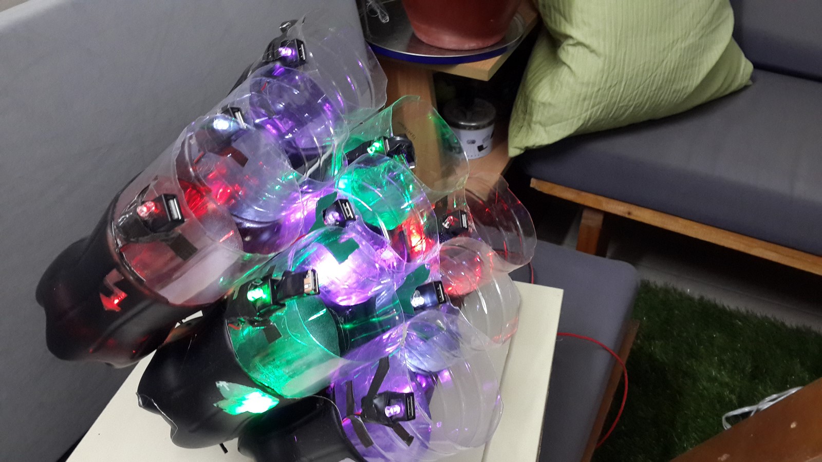
Eventually I put all the leds between the two bottle parts, so they light the transparent parts of the bottles, which was very impressive in the night:
Conclusion
To conclude both parts of this project I can tell it wasn't such an easy job, but I can say that I didn't know almost anything from the theory I wrote here and have learnt a lot on the way. I think that after building the panel or if you just buy a panel you got most of the hard work. The other parts are pretty simple in order to make the station to work. At the end of the day it just depends on what features you would like to add to your station. Green energy is the future! It is cool to have this "machine" at home which produces energy by doing nothing - So go and build one!
Any suggestions/questions/corrections? Let me know!
AA