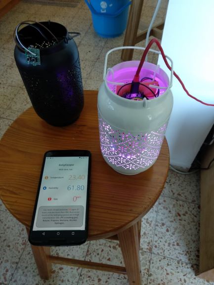
We have reached that age where friends and family around starting to have babies. Giving my friend’s project, I've decided to build some nice gifts, and via these gifts, dive in for the first time into the Arduino/IOT world.
Well, the project is A baby sleeping-environment-sensing and climate-control(TBD). Projects main idea was inspired by Amir’s great post.
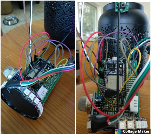
Components:
- ESP32 (note that Amir’s tutorials is with esp8266)
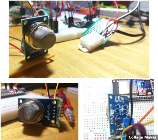
- dht22 / am2302 temprature & humidity sensors
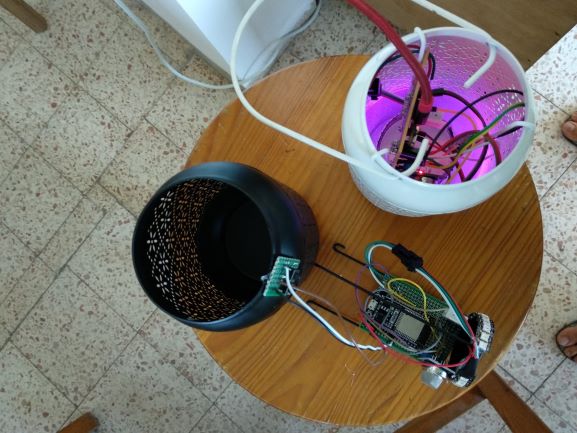
- ws2812 led strip
- ws2812 connector
- ir transmitter (for AC) - didn't used them eventually
- MW2 smoke detector
- power supply & usb cable
Total amount of 32 dollars.
This is the first time I'm making an Arduino project, let alone messing with the ESP32, moreover - building an IOT device, with sensing and posting sensed data to a local server. I must say that every component, and every piece of code, there's huge amount of documentation and tutorials. All is left is to read and explore this magnificent world.
knowing how easy it is, only make me eager to start my next project (an esp32-radio). but as we say in Arabic; "every dog has its day" :)
In this post I will describe the assembly of this project, but also a lot about the code and problems I encountered on the way.
For projects code, refer to my github. The code is well documented, so there's no reason for code break-down in this tutorial, also pins connection explained there more thoroughly.
Getting Started
First some tools that I used in this project:
- ESP32_pinout usage, (SUPER IMPORTANT!, i had a lot of headache until I've read the post entirely and found out some non trivial information there..)
- SPIFF - (I've needed to update the esp32-core to version: 1.0.2, in order to make it work).
Second, things i needed to learn for this project:
- learn how to work with am2302 sensor - DONE
- learn how to work with MQ2 sensor - DONE
- learn how to work with neopixel - DONE
- learn how to work with web interface and the esp32:
- get sensor readings via this tutorial - DONE
- send IR commands - TBD
- read IR commands (from AC remote) and save them - TBD
- add OTA capabilities - (SP32 Over-the-air (OTA) Programming – Web Updater Arduino IDE and this). - TBD
- bring-up server via hotspot if wifi not connected - DONE
- be able to change setting via web interface - NVS - using this tutorial(and keep changes between restarts):
- change WiFi credentials - DONE
- change AC commands for IR - TBD
- change led RGB- DONE
- change led brightness - DONE
- set night-light led-value & brightness & timer - TBD
- set day-light led-value & brightness & timer - TBD
- present LED RGB status (on the web) - DONE
- add physical buttons:
- Interface for giving the user last IP number by blinking (if user have forgot the IP..). - DONE
- Reboot button. - DONE
All these things might be trivial for a skilled Arduino Maker, but a novice such as I, not quite so. While the software is not the issue here for me, getting hands-on with the sensors and the ESP32 GPIO pins, was quite thrilling!
MQ2
At first I tinkered with it via this simple tutorial, where they used simple analog reading and a "dumb" alarm that is being triggered when value is above some threshold.
While this is nice, and can be useful for a generic-gas-detector-alarm, I wanted to get something more accurate from this sensor.
After looking at the sensor data-sheet, there's a table explaining exactly how to extract specific gasses ppm measurements out of a single analog sample:
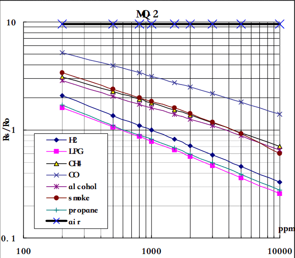
The MQ-2 smoke sensor is sensitive to smoke and to the following flammable gases:
- LPG
- Butane
- Propane
- Methane
- Alcohol
- Hydrogen
The relationship between voltage and gas concentration is the following:
- The greater the gas concentration, the greater the output voltage.
- The lower the gas concentration, the lower the output voltage.
Note on ADC2 GPIO pins: ADC2 pins cannot be used when WiFi is used. So, if using WiFi and having trouble getting the value from an ADC2 GPIO, you may consider using an ADC1 GPIO instead, that should solve your problem.
Note on CO: The health effects of CO depend on the CO concentration and length of exposure, as well as each individual's health condition. CO concentration is measured in parts per million (ppm). Most people will not experience any symptoms from prolonged exposure to CO levels of approximately 1 to 70 ppm but some heart patients might experience an increase in chest pain. As CO levels increase and remain above 70 ppm, symptoms become more noticeable and can include headache, fatigue and nausea. At sustained CO concentrations above 150 to 200 ppm, disorientation, unconsciousness, and death are possible, Here some more information:
Concentration and its source from wikipedia:
- 0.1 ppmv - Natural atmosphere level
- 0.5–5 ppmv - Average level in homes
- 5–15 ppmv - Near-properly adjusted gas stoves in homes, modern vehicle exhaust emissions
- 17 ppmv - Atmosphere of Venus
- 100–200 ppmv - Exhaust from automobiles in the Mexico City central area in 1975
- 700 ppmv - Atmosphere of Mars
- <1000 ppmv - Car exhaust fumes after passing through catalytic converter
- 5,000 ppmv - Exhaust from a home wood fire[59]
- 30,000–100,000 ppmv - Undiluted warm car exhaust without a catalytic converter
MQ2 sum up:
At first I've tried to read from analog_input and interpret all value of the measured gas, after many attempts from different tutorials, it turned out to be too much complicated, so I've decided to implement the gas measurement in the “fast and stupid” way:
Simply - i am measuring values from analog input, and when value is above some threshold (300 ppm), im alerting. These threshold has reached by experiments with a lighter, and the MQ2 respond to gas.
Yes, the same way as the simple tutorial, gotta choose my fights man..
Note on MQ2 voltage: The sensor operate on 5v, while the ESP32 GPIO pins work on 3.3v, so i user a simple voltage divider, whis 470Ω and a 1kΩ resistors
NEOPIXEL
 This is not part of the project but im using it to learn the work with neopixel. to learn by the way how to work with HC-SR04 sensor.
Finally I've used this tutorial for making the device work. After installing the Adafruit neopixel library, I've got the leds working, and it was nice.
Than I've noticed that they are flickering and acting weird, at first I thought it was an electrical problem (because I have connected the led without the capacitor as instructed here, only a 470Ω resistor at the DATA channel), after a few tries for making the connections better, I've decided to google it (yeah I know, should've done that first).
It appears that the problem is when using the ESP32 with NeoPixel & WiFi, I didn't realized that Amir, used a Blynk library, meaning the server is actually not on his ESP8266, Where i'm using Async-Server library, for hosting the web servers POST and GET requests, moreover, reading from SPIFF the html and CSS.
I’ve discovered that the cause for flickering was the Adafruit_NeoPixle library, it just didn't handled interrupts correctly, so WiFi communication got in the middle of LED operations. after changing to NeoPixelBus, everything worked out perfectly!
Another problem I've encountered:
when calling BreathingEffect(), the diming changes LED color - there is a closed issue about this here, and a workaround for this problem.
Non volatile memory
Preferences library is a wrapper around NVS, it is neat and
it appears quite easy to use (tutorial). I’ve added BabySleeperinit.ino - for first initiation if someone want to tinker with the project, you can upload the BabySleeper_init sketch first, filled with ssid and password, and that it'll connect to WiFi without a problem.
For the novice user (non developer), I'm setting hot-spot (SSID: BabySleeper, PASS: BabySleeper). If initiated, leds light will be solid orange, after connecting, type in the browser 10.10.10.1, and through there, set the correct WiFi credentials.
Physical buttons:
The lack of screen made me find a clever solution for interfacing with the user, when WiFi not connected (thus no web interface). I’ve connected 2 simple push-buttons to an interrupt routine, so that there's an immediate response for pushing them, this is quite straightforward.
Note on ISR (Interrupt Service Routine):
When called, everything else is halted. including ESP32's inner watchdogs, hence it'll be a good practice to perform as little as possible inside an ISR.
Note on push buttons GPIOs:
At first I’ve connected one of the buttons to pin 2 (also where ESP32 blue-led connected to).
Than set the pin to be pull-up pin, and attached the interrupt type “falling” in the arduino sketch. the ESP32 couldn't interrupt correctly when pushed, it didn't caught the falling voltage change. i think it is because the ESP32-blue-led, which also connected to this pin.
After changing to some other pin, interrupt received correctly, and everything worked great!
BabySleeper Manual:
BabySleeper Light messages protocol:
- At boot - red color “breathing” - device will try to connect to wifi.
- Success - solid green for 3 seconds.
- blink in blue the number of last digit of IP (e.g: if given ip is 192.168.1.8, than device will blink in blue 8 times)
- Fail - solid red for 3 seconds, than solid orange - indicate that device is in hotspot mode. User should connect to hotspot name “BabySleeper” with password “BabySleeper”, type the following Address: 10.10.10.1 in your browser to enter WiFi credentials. After pressing OK, device will reboot and try again.
- Success - solid green for 3 seconds.
Small black buttons:
- If device is connected and user wish to know device IP. Pushing on the green button will blink in blue the number of last digit of IP (e.g: if given IP is 192.168.1.8, than device will blink in blue 8 times), after that user can enter the following IP in his browser: 192.168.1.X, where X is the number of blue blinks.
- The second button is for restarting BabySleeper.
Troubleshooting:
- If light is bright white, without any effect. than a hard reboot is required: simply plug off the USB cable, and plug it back in.
Project summary:
In one sentence it'll be “from zero to hero” :)
Before this project i had zero knowledge about Arduino nor ESP32, not working with sensors not working with jumper wires and soldering.
I did knew that everything is learnable through google, and that was my starting point.
At first, I've learned how to turn on a led, than how to measure analog input from pins, than learned about GPIOs and their purposes, what pin can and cannot do, later on I've learned how to build a server on the ESP32, and so on. In baby steps, I've learned what I needed for this project, at the end, all I had lest, is to connect all the pieces together.
Now I can confirm that I have a solid basic-knowledge of the Arduino world and some of its surrounding. Future project will be much easier and faster for me, and i know for fact that Im only getting started with this world, there’s much to learn, and a lot of interesting ideas to implement.
I know now for sure that everyone can make Arduino projects, there’s a huge community, and almost everything is beautifully, impressive and generously documented.
So go on, buy some Arduino capable card and dive in.
Cheers, Gal
P.S
My github code is well documented, so there's no reason for code break-down in this tutorial. enjoy :)