Last year we celebrated my daughter's first birthday, and as a present I've built her a busy-board and described all the build up on this post. During the build-up I left a lot of upgradeable parts such as knobs, switches, screens which weren't operated at the time. On this post I'll describe the upgrade I made for my daughter's second birthday.
I ended up doing less upgrades then I planned to since I encountered some software issues that took me some time to understand and solve, so I decided to focus on a modest but very nice upgrade.
As always, here is a description and some videos of the new features:
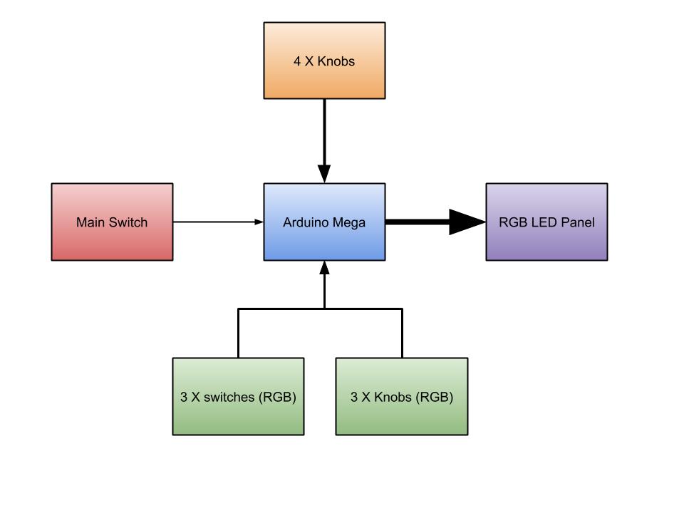
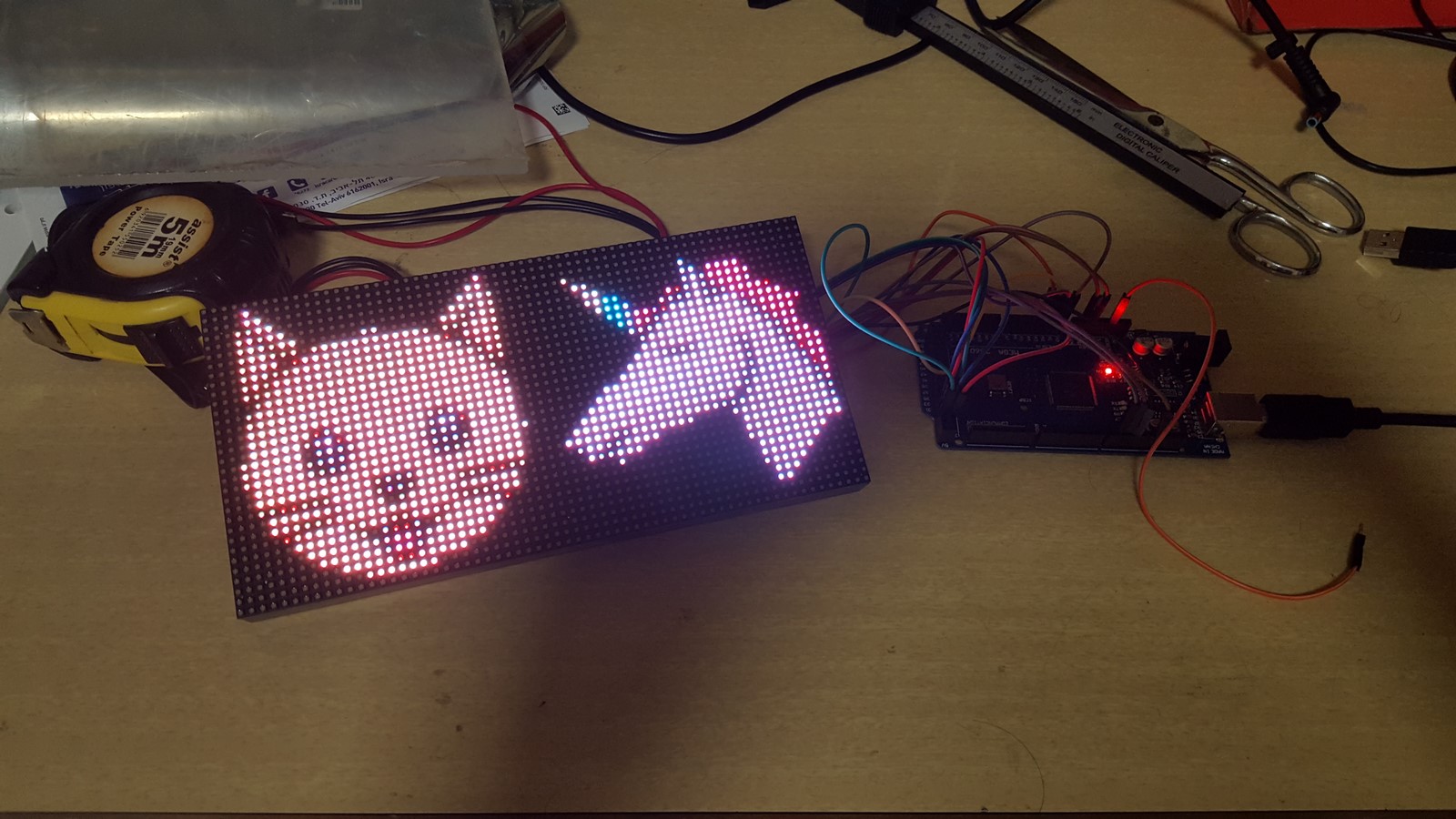
- 32x64 RGB panel, powered by an Arduino Mega.
- There are 4 knobs, 2 for each 32X32 pixels which controls the images (or icons).
- First knob changes the icons "family" type (animals, shapes, clothes, numbers etc.).
- Second knob switches between icons in a chosen family.
- When the first knob reaches to its maximum value, all icons disappear and you get a blank drawing board, and by using the other knobs you can control the pixel's horizontal and vertical location and can draw freely.
- Three more knobs and switches are located on the bottom of the panel. They control the red, green and blue colors in some of the images and can change those images' color when played with.
- Main switch to power on/off the board.
Icons:
Free drawing:
Numbers:
Working With A LED Panel
The 32X64 RGB led panel can be ordered from Adafruit and also from AliExpress, and can come in many sizes, from pixel size of 2.5mm to 10mm. For my project I have used the 3mm panel since it fitted perfectly on my busy board.
The panel has input pins and output pins so it is possible to make a serial connection between the output of the panel to the input of another similar panel and make a larger panel.
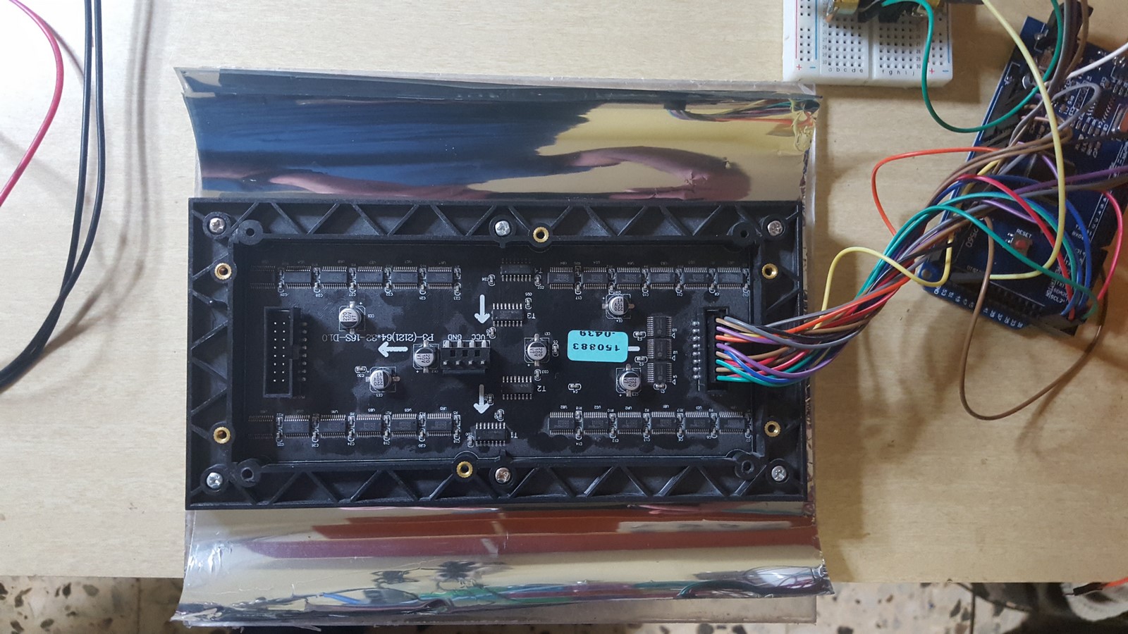
As you will read on this post, if you going to use an Arduino to control this panel, you might avoid connecting several panels in series since controlling more pixels takes more time and using an Arduino with a low processing power make the entire program very slow.
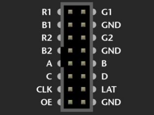
There are many websites which explain how to connect the board, I have used this PDF which shows the connections step-by-step. To summarize this PDF, the connections using an Arduino Mega are:
- 3 ground pins ---> Ground
- R1 --> Pin #24
- G1 --> Pin #25
- B1 --> Pin #26
- R2 --> Pin #27
- G2 --> Pin #28
- B2 --> Pin #29
- A --> Pin #A0
- B --> Pin #A1
- C --> Pin #A2
- D --> Pin #A3
- LAT --> Pin #10
- OE --> Pin #9
- CLK --> Pin #11
The board itself is powered by voltage of 12V. Next, you can download the Adafruit matrix panel library using the library manager:
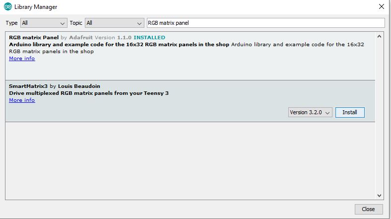
and use the "test shapes 32x64" example" to test that everything is working:
If the demo is working, you can start using this library to build your project.
Software
Making and Drawing Icons
Back to the Adafruit demo, if you'll check the "PanelGFXDemo" demo, you'll notice they included another file smileytongue24.h, and in this file they defined a very large array on the using PROGMEM:
const unsigned short bitmap24[576] PROGMEM={
0x0000, 0x0000, 0x0000, 0x0000, 0x0000, 0x0000, 0x0000, 0x0000, 0x0000, 0x0000, 0x0000, 0x0000, 0x0000, 0x0000, 0x0000, 0x0000,   // 0x0010 (16) pixels
...
...
...
0x0000, 0x0000, 0x0000, 0x0000, 0x0000, 0x0000, 0x0000, 0x0000, 0x0000, 0x0000, 0x0000, 0x0000, 0x0000, 0x0000, 0x0000, 0x0000,   // 0x0240 (576) pixels
};
What you see here is actually a 36X16 image, written in a hexadecimal form. Each pixels is represented by 16 bit ("short") such that red gets 5 bits, green gets 6 bits and blue gets 5 bits (5-6-5 system). In the Arduino code, a function gets a pointer to this array and the sends the data to the panel such that the image is drawn by the pixels. Later on I'll show another function I used which translates images which are constructed as 4-4-4 bits format to 5-6-5 bits (12 bits to 16 bits) so images can be saved as 12 bits data as well (Red/Green/Blue each defined by 4 bits). I used this system since it was easier to create an image when the bits amounts are equal.
Two things worth mentioning:
This array is define using the "PROGMEM" command which means it is not part of the program but it is flashed on the flash memory of the arduino board.
This example image size is around 9.2 Kilo bits, which is not a lot to deal with compared to the computing powers of today but for the arduino it is quite a lot to handle, so showing an image is possible but making full animation is a bit problematic for an Arduino and can be solved using ESP32 or a Raspberry PI.
The core of my projects was to download many icons and draw them on the panel, so the first code I wrote was a python code which gets an image and desired size and produces the 4-4-4 bits format of this image so it can be easily copied to the arduino code.
The code I wrote does the next:
- Gets a folder with all folders of images and desired final size (32x32 in my case). The folder structure can be seen here
- For each folder in the main folder, it transforms all images into 4-4-4 bit format, and write them as an array of arrays which can be instantly copied to the arduino code.
Creating the 4bits image requiring only few lines of code:
import cv2
import numpy as np
SIZE = 32
bitsP2M1 = 15 #(2^4-1)
TRANSPERCY2BLACK = True
img = cv2.imread(imgFullPath,-1)
img = cv2.resize(img,(SIZE,SIZE))
if TRANSPERCY2BLACK:
    img[np.where(img[:,:,3] < THRESH4BITS[curr_dir.name])] = 0
img_4_bits = (img.astype('float') / 255.0 * bitsP2M1).astype('uint8')
In this code I'm using the OpenCV and Numpy libraries to do the following:
- Read the image from a file.
- Resize the image to the desired size (32X32).
- Paint the background in black (So the background leds will be off).
- Take the 8 bit image and for each color divide its value by 255 and multiply by 15, thus leaving only 4 bits representation of each color.
In the rest of the code I used several other libraries to take only 4 bits from each color, join them together to a string and print them. The output can be seen in this code and looks something like that (I'll explain about the "HIGH PROGMEM" later on):
static const uint16_t HIGH_PROGMEM
                 animals[][1024] = {
{0x000, 0x000, 0x000, 0x000, 0x000, 0x000, 0x000, 0x000, 0x000, 0x000, 0x000, 0x000, 0x000, 0x000, 0x000, 0x000, 0x000, 0x000, 0x000, 0x000, 0x000, 0x000, 0x000, 0x000, 0x000, 0x000, 0x000, 0x000, 0x000, 0x000, 0x000, 0x000,
...
...
...
0x000, 0x000, 0x000, 0x44c, 0x44c, 0x44c, 0x44c, 0x44c, 0x44c, 0x44c, 0x44c, 0x44c, 0x44c, 0x44d, 0x44d, 0x44d, 0x44d, 0x44d, 0x44d, 0x44d, 0x44d, 0x44d, 0x44d, 0x44d, 0x44d, 0x44d, 0x44d, 0x44d, 0x44d, 0x000, 0x000, 0x000,
},};
Using this representation in the Arduino code can turn these images (taken from www.flaticon.com):


to this:
In my repository you can find all the images I have used, all of them were taken from www.flaticon.com which has all the rights to these images.
PROGMEM - The 32K and 64K problems
Let's talk about the "PROGMEM" command on Arduino and start with an description from the main Arduino website:
Store data in flash (program) memory instead of SRAM. There’s a description of the various types of memory available on an Arduino board.
If we check the types of memory available on an Arduino board we will notice this table:
| ATMega328P | ATmega2560 | |
|---|---|---|
| Flash (1 kByte used for bootloader) | 32 kBytes | 256 kBytes |
| SRAM | 2048 bytes | 8 kBytes |
| EEPROM | 1024 bytes | 4 kBytes |
And now we get to the main reason I used an Arduino Mega for my project. Arduino Uno usually has an ATMega328P chip and therefore has 2KB for the program and variable and 32KB flash memory for everything else. The Arduino Mega has an ATmega2560 chip with 8KB for the program and variables and 256KB flash memory.
Looking back to the last section, I was trying to create 32X32 icons with 2 Bytes for each pixel (16 bits), so a single icon needed memory size of 32 X 32 X 2 = 2048 Bytes. That means that the Arduino Uno can hold around 16 icons (actually a bit less since the flash memory is not empty... ) and the Arduino Mega can hold around 128 icons. I used 95 icons in my code so Mega was the right choice. When flashing the program you can see the amount of memory your program takes:

Here you can see the program and variables takes 2720 Bytes which are 33% of the 8KB SRAM available, and the PROGMEM variables, which consists of all the icons, takes 212808 Bytes which are 83% from the entire flash memory. By the way, flashing data to the flash memory is relatively slow, so while testing the code I have used only several icons and added the rest only to the final version of the code.
During my build-up I encountered two PROGMEM related issues which I would like to explain here. This part as a bit more "software-technical" so feel free to skip it if you are not into this kind of stuff, but make sure to read the bottom line if you intend building a similar project.
The 32KB Array Issue
When I was printing the icon array using my python script for the first time, I defined all the icons as a single array and planned to address them by numbers. Then, when compiling and flashing the code on the Arduino Mega I received the next error:
error: size of array 'images' is too large
After reading about this subject on some forums it occurred to me that when writing an Arduino program you can't define an array to be with more than 32768 (2^15) elements since the pointer which is used to find an element in an array is of type int16 which means it can only "point" to 2^15 different numbers (I would expect 2^16 but these are the facts so they might have used int16 instead of uint16).
Bottom line - I had to divide my array to several arrays according to the icon topics/families, where each array holds around 10 icons which summed up to about 10K elements per array. You can also see it in the python code implementation I wrote.
The 64KB Memory Location Issue
After solving the first issue, I transformed all the icons as several arrays and wrote a test code which prints the icons to the RGB panel one by one. The first icons where shown properly but after a while, instead of certain icons, other icons were shown or even worst - Just some weird noise of colors were shown on the LED panel.
After digging deeper into the subject I learned about the Program Space Utility code which is normally included in every Arduino code you'll write. This is the code that consists of all the functionality of reading data from the flash memory. After reading some more I realized that when using a variable which was defined with PROGMEM, the Arduino will use the pgm_read_word_near command to read the data, and this command expects a uint16 pointer type which points the data address. Once again, this pointer can point only to 2^16 different addresses - Meaning that when I wanted to get a pointer to an icon which is located around the 66K flash area the pointer used by the function was equal to 66K-2^16 which was around 1K, and then it points on other icons or even the program itself.
In order to fix this problem I've used the pgm_get_far_address functionality which yields a uint32 pointer that can point to all the Mega flash memory space, and pgm_read_word_far to read the data from that address. I defined a new function which receives a pointer to an icon family, the icon position in that family array and its size and read it into the program memory:
  void getFarImage(uint32_t ptr, int array_pos, int len) {
    for( int i=0; i<len; i++)   img[i] = pgm_read_word_far( ptr + 2*array_pos*len + (2 * i));
  }
In order to get the pointer I call this function as follows:
        switch (iconSet) {
        case 0:
            getFarImage(pgm_get_far_address(animals),bmp_num,RGB_BMP_SIZE_SQ);
            break;
        case 1:
            getFarImage(pgm_get_far_address(cars),bmp_num,RGB_BMP_SIZE_SQ);
            break;
        case 2:
            getFarImage(pgm_get_far_address(emoji),bmp_num,RGB_BMP_SIZE_SQ);
            break;
        case 3:
            getFarImage(pgm_get_far_address(food),bmp_num,RGB_BMP_SIZE_SQ);
            break;
        default:
            getFarImage(pgm_get_far_address(animals),bmp_num,RGB_BMP_SIZE_SQ);
            break;
        }
Where the names animals,cars,etc. are the icon families I defined in bitmaps.h the bmp_num is the number of icon in the array and the RGB_BMP_SIZE_SQ is 32*32(=1024). I'm sure there are faster ways to implement what I've done, I tried it with the memcpy command but that didn't work because the data is on the flash and not on the RAM.
But after fixing all these issues still something wasn't right. I ran the code, the icons were displayed properly, but from time to time the Arduino got stuck and reset itself. I read a bit more about that issue and figured out there was a third problem - Since I'm defining the icons before defining most of the software, the software itself is now located on the higher parts of the flash memory and needs a uint32 pointer to be executed and therefore doesn't work fluently and sometimes even reset itself.
The solution to this problem is easy. Apparently you can choose where in the flash memory you would like to store your variables. When we define a variable in the flash memory we usually write:
static const uint16_t PROGMEM
                 animals[][1024] = { ... }
Instead, if we will write:
static const uint16_t __attribute__((section(".fini7")))
                 animals[][1024] = { ... }
The compiler will try to write the data to the highest place possible on the flash memory, leaving the program on the lower parts.
In my code, you'll notice I've defined a new word:
#define HIGH_PROGMEM __attribute__((section(".fini7")))
and when defining my icons I simply used it as follows:
static const uint16_t HIGH_PROGMEM
                 animals[][1024] = { ... }
After this final fix all the flash memory calls were finally working perfectly!
Wiring
The wiring is as follows:
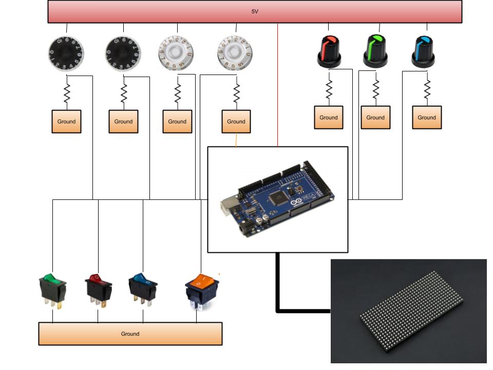
The precise pins' connections are defined on the defines.h file:
// ################# PINOUT ######################
#define CLK 11 // USE THIS ON ARDUINO MEGA
#define OE   9
#define LAT 10
#define PANEL_A   A0
#define PANEL_B   A1
#define PANEL_C   A2
#define PANEL_D   A3

#define MAIN_PIN 4
#define RED_SW_PIN 7
#define GREEN_SW_PIN 6
#define BLUE_SW_PIN 5
#define BUTTON_NAME_PIN 3

#define ICON_CHANGE_LEFT_PIN A4
#define ICON_SET_CHANGE_LEFT_PIN A5
#define ICON_CHANGE_RIGHT_PIN A6
#define ICON_SET_CHANGE_RIGHT_PIN A7

#define RED_PIN A8
#define GREEN_PIN A9
#define BLUE_PIN A10
Notice that each of the knobs is actually a potentiometer and is connected to the an analog input on the Arduino, therefore it needs another resistor in series to create a voltage divider (which I have already explained about in many of my posts in the past).
The switches need only a ground connection since they are connected to the Arduino using a pull-up resistor. From the setup() code:
  pinMode(MAIN_PIN, INPUT_PULLUP);
  pinMode(RED_SW_PIN, INPUT_PULLUP);
  pinMode(GREEN_SW_PIN, INPUT_PULLUP);
  pinMode(BLUE_SW_PIN, INPUT_PULLUP);
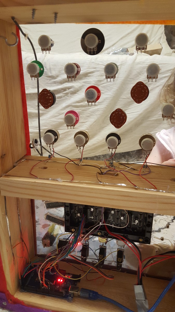
This is the front view (right-side) of the board, where I connected all the parts:
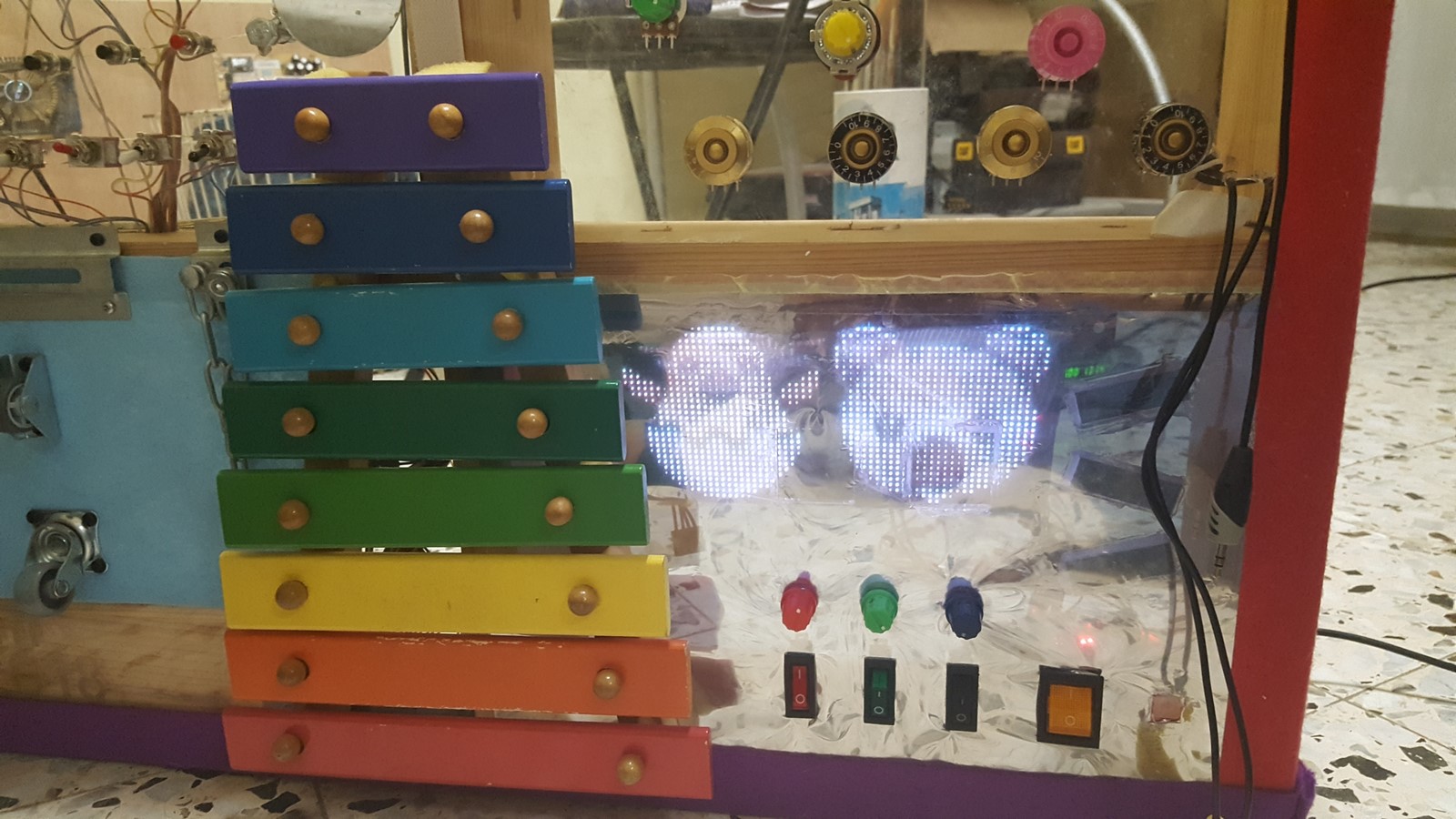
Notice I put a reflective mirror cover behind the perspex cover. I made this for two reasons:
- When the panel is off - You neither can see the panel nor its wiring.
- When the panel is on - It is less bright than without the cover. With several layers of this cover I could control the brightness just I wanted. This could have been solved by controlling the LEDs' brightness but since I've used only 4 bits per color per pixel I didn't have much brightness resolution to play with.
On the back side, I mounted the Arduino on the board's bottom part and connected the panel and the switches, and the power came from the other side of the board where I already mounted it on the first version of this project.
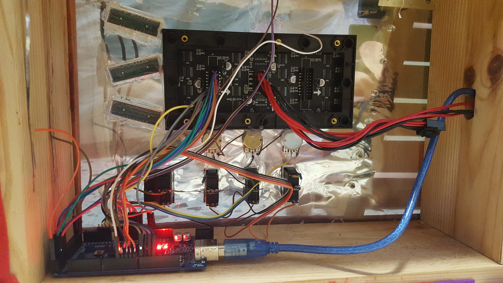
In order to avoid a lot of wiring while connecting the knobs on the upper part of the board, I put two conductive lines (mostly used for solar panels) which passes 5V and Ground along the board, and I only needed four wires going back to the Arduino analog inputs.
That was all the wiring! The matrix panel wiring could have been done nicer using the special wire came with the panel but since it was already working I didn't touch it :)
Code
The Code consists four files:
- bitmaps.h - All the icons.
- defines.h - All the pinout definitions and hard-coded parameters.
- classes.h - All the classes used in this code.
- RightCode.ino - The main code.
In this code I have also used the Adafruit RGB matrix panel library and another .h file for Hebrew fonts.
In the class code I created several functions which help me simplify my code.
class VoltageDivider {...}
I've noticed that in order to control my projects I tend to use voltage dividers a lot, usually by using potentiometers. So I created a class for all the needed computations using these dividers. You can initialize this class with the Arduino analog pin, the input voltage it has, the constant resistor value, and the location of the potentiometer. The class will use the analog input value and can calculate the real resistance value of the potentiometer.
Notice that when using a voltage divider, the analog readings on the arduino will changed in a non-linear transition while turning the potentiometer knob (since the equation is not linear). Using the real resistance value can help making the control more linear.
class VoltageMapper : public VoltageDivider {...}
The VoltageMapper class is the same as the VoltageDivider (inherits its class), only with an added functionality of mapping the resistance values into requested values.
For example, let's say I have 8 icons which I want to switch between when turning the knob, and the potentiometer can vary between 0 Ohm and 10000 Ohm. In this case the VoltageMapper will map the numbers 0-10000 to 0-7. The mapper can also raise a flag if the mapped value has changed from it last reading and preform some hysteresis to make sure some analog noise will not make the icons be frequently switched forward/backward.
class my_RGBmatrixPanel: public RGBmatrixPanel {...}
This class contains several more functions I've added to the Adafruit LED matrix library. Among them:
paintFree- A function that compares between the last and the current pixel locations and draw a line between them. This is used for the "free drawing" part.fixdrawRGBBitmap- A function that turns 4-4-4 bits RGB representation to 5-6-5 bits RGB representation. I've mentioned why it is needed on the LED panel part.getFarImage- A function to get icon from any part on the flash Memory. I've mentioned that on the PROGMEM part.display_rgbBitmap- A function that receives the icon family, icon number and position and displays the chosen icon on the matrix panel.printHebandprintHebStr- Functions to display Hebrew (Or any non-latin letters) on the screen. This one is a bit tricky. If you want to draw any non-latin letters, the ASCII code you'll need might be more than one byte per letter, so reading a string char-by-char will lead to undesired results. Instead, you have to read the first char, understand it is a Hebrew Unicode, and then draw the second char using Hebrew fonts. At first I meant to draw the Hebrew letters by myself but then I found this great article where someone has already implemented those letters for an OLED display. The OLED display library is using the same Adafruit matrix library so the code was working on my panel as well.
The main code is pretty simple. I read the values from the knobs and switches and changed the icons according to their values. If the "family icon" knobs are turned all the way, the program switch to a new functionality which reads the values of the icon-choosing knobs and make them control a pixel on the screen - thus create a drawing board for "free" drawing.
What Next?
There are still many electronic parts which are not connected which I can use in order to upgrade the board. Also, the icon refreshing on the panel is working very slowly and it can be speed-up using an ESP32 or a Raspberry Pi. Have any ideas I can continue with? Would love to hear!
AA