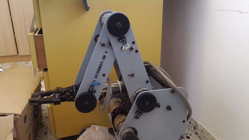
About two years ago I got Scorbot from a junk yard. One of the first posts I wrote was dealing with Scorbot first moves. At first I thought it is just junk and I will harvest it for parts. Then, as I continued checking it, I found out this 25 years old piece of metal actually functions completely perfect and apparently was thrown since its controller wasn't working or it wasn't supported anymore. After some reverse engineering I completely understood how to control Scorbot and the last part of the post I've mentioned above was dealing with some test cases which proved to myself all Scorbot functionalities are working - Six Motors, Five encoders and Five micro-switches. Since then I haven't touched Scorbot, I disconnected its wires when moving to a new flat and was too lazy to connect all the wires again. During this time, a few people addressed me via this blog or through Facebook and I found out I'm not alone - Many people tried to do the same and resurrect their own scorbot. Most people got to the same part I got and had some difficulties to continue. I saw my post had helped people and always thought about continuing it.
Then, on a whole different issue, Geekcon was coming up, and it was time to find a new useless project to build at this event. We sat down for a beer, and I don't remember who had the idea, but someone suggested we should make scorbot into a caricaturist, meaning it will take a picture of a person and will draw it. Everyone thought this idea is awesome, including me of course since it was finally a good excuse to clean Scorbot, oil its motors and continue the unfinished work.
Jumping to the last day of Geekcon - We sort of made it! Scorbot cannot draw people yet, but it can definitely get a photo from the internet and draw it. Unfortunately I didn't take a lot of videos during Geekcon, but I managed to assemble this short video which shows the three-days progress.
The project name was Chappie - As a tribute to Chappie, from the movie... Chappie! If you haven't seen it, check these 10 seconds from the trailer to understand the point.
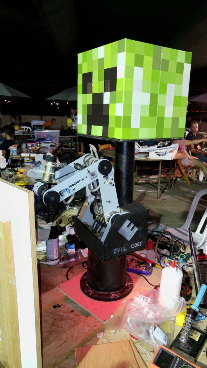
Also, thanks to Pepe, one of our team members, Scorbot got a new wood casing and was branded as a product of Evil Corp, and also a head from Minecraft (Actually we just brought all the junk we had at home).
In this post I will share everything we've done - Hopefully it will help more people who found a lonely scorbot to give it a cozy home and make something cool out of it.
The Arduino Shield
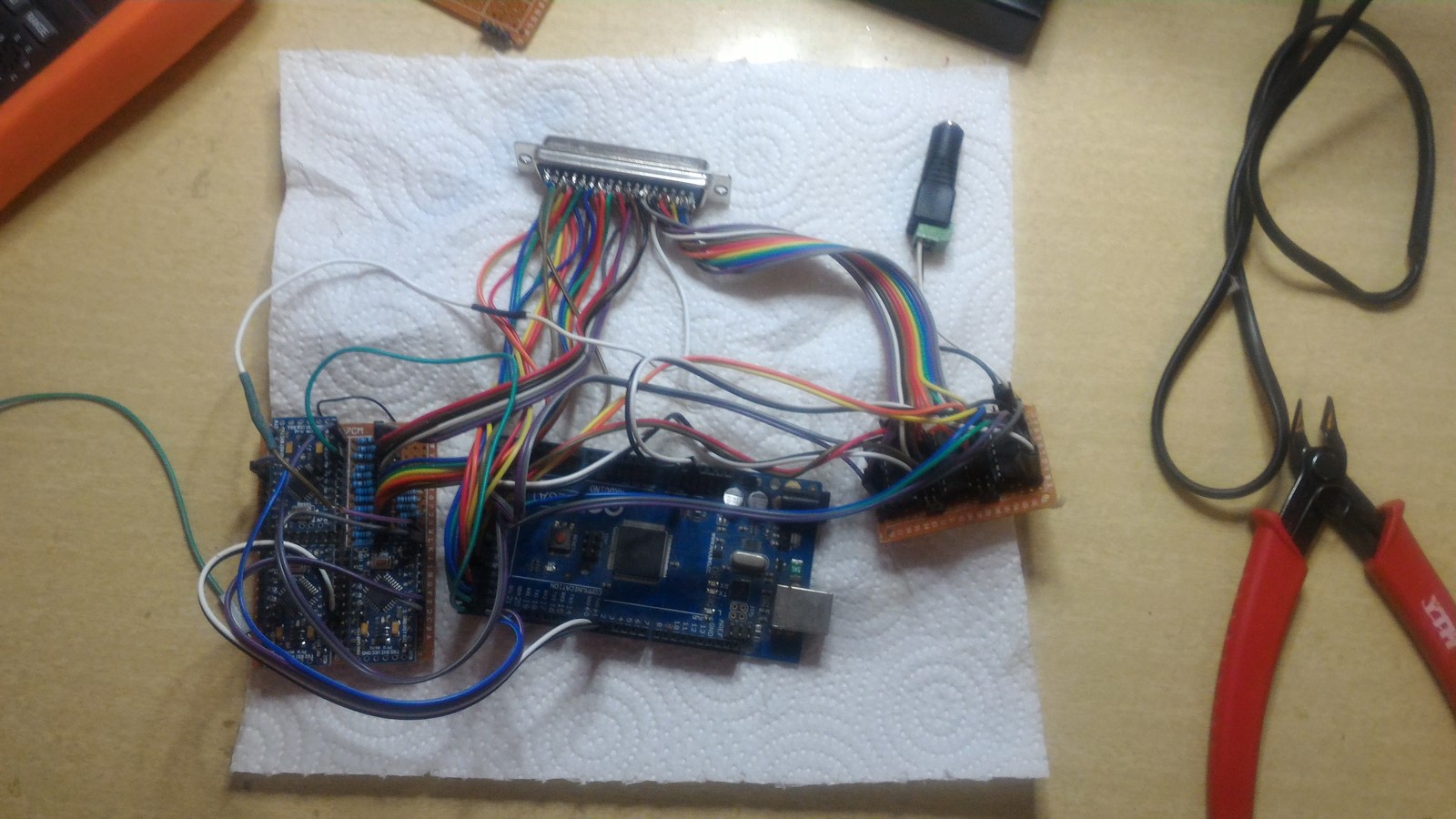
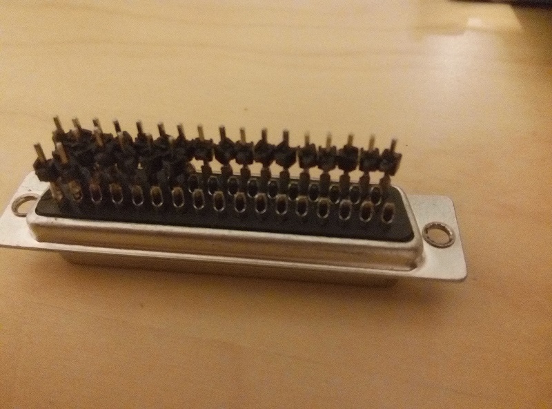
One of the main issues with getting back to work on Scorbot after two years, was the wiring. It has a 50 pins connector so it was really hard to reconnect everything.
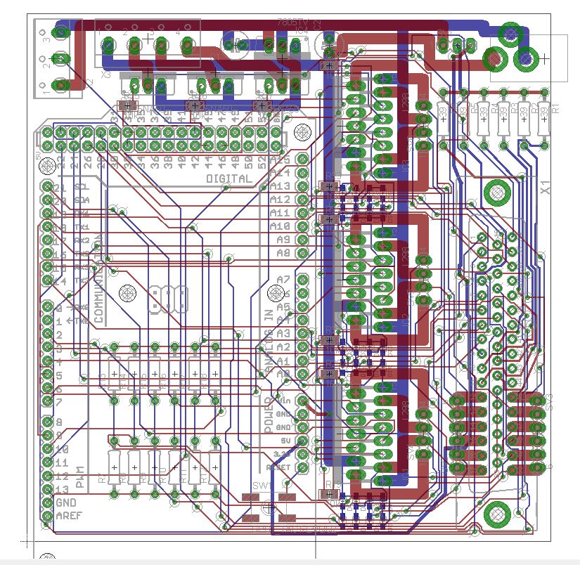
Luckily, one of our team members had designed a really cool shield for Arduino Mega, based on my original scorbot post. Above I've linked the Eagle files of the design if you want to order it. This is how the Eagle design looks like:
After the shield has arrived, the components were soldered. The 50 pins connector was a bit problematic to solder since it has 3 rows. To do so, my friend has made the connector a bit longer and then solder it to the board.
Finally, I could throw away the old wiring and use the new one.
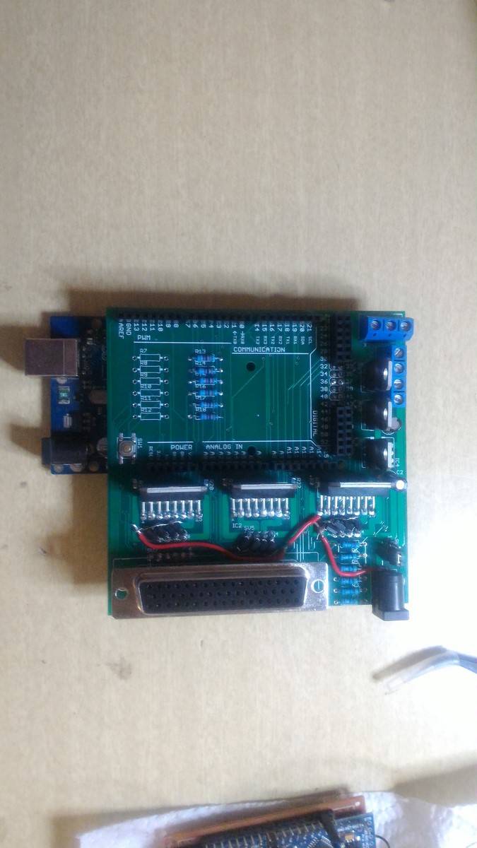
The shield has three L298 drivers, and connects between all the scorbot pins and the drivers/Arduino. The shield also supports the use of both non-addressable and addressable LED strips (The 3 transistors at the back) since adding LED lights to your project always makes it better. The only thing this shield lacks is a PWM connection to the ENABLE of the drivers, so the motors could work at different speeds - We just forgot about it!
Using this code which just move all the six motors we were able to make a first test of scorbot
Inverse Kinematics
The next thing we wanted to achieve was to have a function which will receive as input $(X,Y,Z)$ coordinates in the real world, and outputs the commands each motor should get. As a person with no background in robotics, I read a lot of papers and saw a lot of YouTube videos about inverse kinematics.
Let's start with a short explanation about forward kinematics. Forward kinematics are mathematical transformations which helps understanding how a $(X,Y,Z)$ point of interest (the pen position in our case) will be affected when changing the angle of each of the motors. Inverse kinematics are basically the inverse matrices of the forward kinematic functions, yielding a transformation from a point of interest $(X,Y,Z)$ back the motors angles, and thus creating the exact function we are looking for.
One way to do inverse kinematics, which I read a lot about, was the Denavit–Hartenberg Parameters. This is a bit complex mathematical way to create any transformation needed between two motor axis. While reading about this method I've realized that most of the parameters are either nullified or constant in my case, which made me realize there should be an easier way to do this procedure.
After arriving to Geekcon and talking to some people, someone said something like "You can probably solve it using simple geometry", so I said to myself why not, lets give it a try. A short time later I drew this page which has everything I needed:
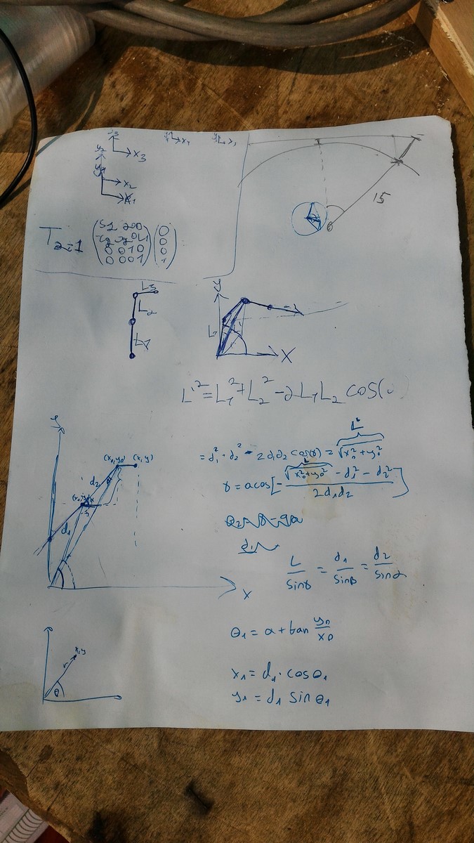
I'll explain here how these calculations work. Let's start from a side-view of Scorbot, and assume we want to get to a $(X,Z)$ position as in this drawing:
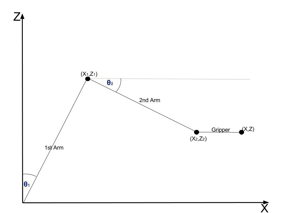
$X$ is the axis from scorbot to the drawing board, and $Z$ is the up/down axis. Scorbot mechanics were designed in a smart way so if we move the gripper to a certain pitch angle, it will stay in that angle even if the rest of the arms will move. This fact really simplifies the problem, since if we decide the gripper is always at a certain angle (say 90 degrees), we only need to control two arms to change the vertical position of Scorbot, which are $\theta_1$ and $\theta_2$ in the drawing.
So lets add some more parameters to the drawing and see how to find $\theta_1$ and $\theta_2$ from a given $(X,Z)$:
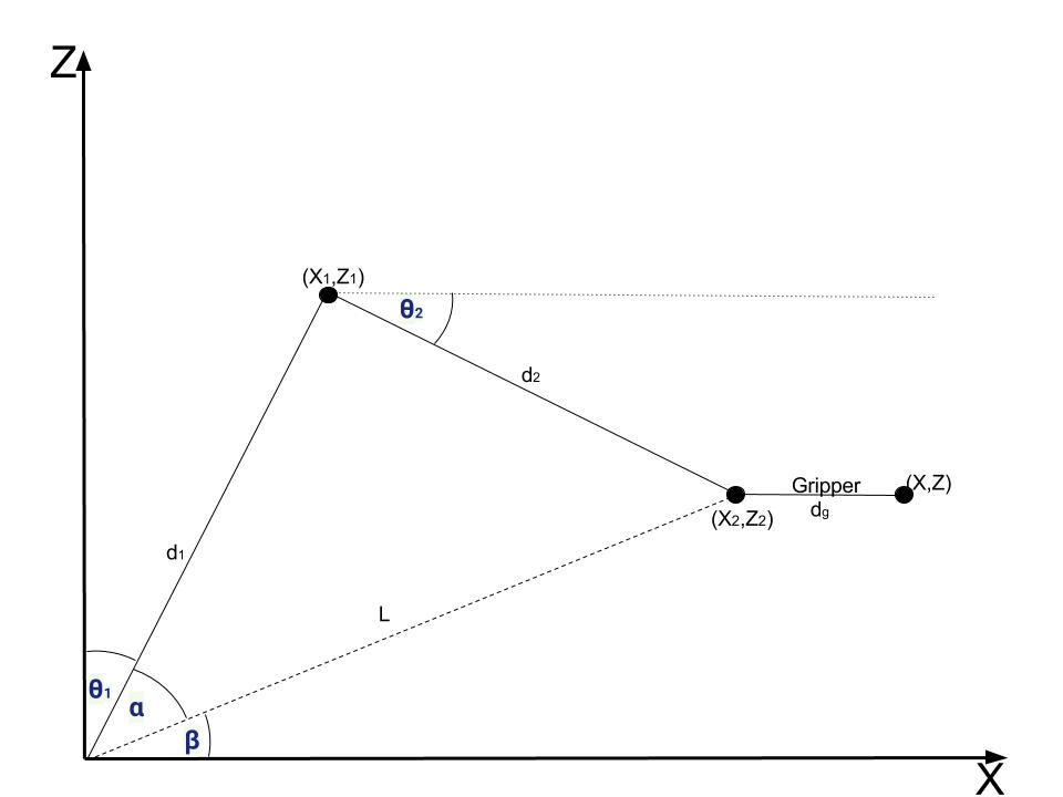
From here to the end of the paragraph there are a lot of equations - If you trust my calculation and just want your scorbot to work you can skip this part and take the final results which are the equations with rectangles around them.
- We start by calculating $(X_2,Z_2)$, which is easy since we know the gripper length $d_g$ and its angle $\theta_g$
$$
X_2 = X - d_g\cdot\cos{\theta_g}
$$
$$
Z_2 = Z - d_g\cdot\sin{\theta_g}
$$
You can switch the minus sign with a plus sign, depends where you start measuring $\theta_g$.
Now we can calculate $\beta$ angle:
$$
\beta = \arctan{\left(\frac{Z_2}{X_2} \right)}
$$
$\alpha$ angle can be found using the Law of cosines:
$$
d_2^2 = d_1^2 + L^2 - 2 \cdot L \cdot d_1 \cdot \cos{\alpha}
$$
$$
\alpha = \arccos{\left(\frac{d_1^2 + L^2 - d_2^2}{2 \cdot L \cdot d_1 } \right)}
$$
And finally we have:
$$
\boxed{\theta_1 = \frac{\pi}{2} - \alpha - \beta}
$$
In order to find $\theta_2$ we first find $(X_1,Z_1)$:
$$
X_1 = d_1 \cdot \cos{\left(\alpha + \beta \right)}
$$
$$
Z_1 = d_1 \cdot \sin{\left(\alpha + \beta\right)}
$$
And next:
$$
\boxed{\theta_2 = \arctan{ \left( \frac{Z_2 - Z_1}{X_2 - X_1}\right)} }
$$
So we found the equations when we want to get to a coordinate of $(X,0,Z)$, but since the drawing board is flat and not a sphere, we need to do another small correction when the $Y$ coordinate is not nullified. In this case we need to find $\theta_0$, the angle for the bottom motor, and also add a correction to the $X$ coordinate. In the next drawing, a top-view of Scorbot and the drawing board is shown:
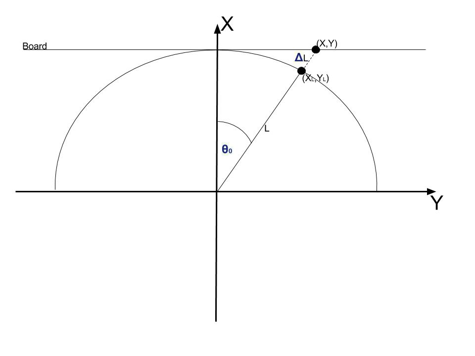
Given $(X,Y)$, finding $\theta_0$ is simple:
$$
\boxed{\theta_0 = \arctan(\frac{Y}{X})}
$$
Next, we should find the changes in the X coordinate. We can do this using the ratio between the two edges of the triangle:
$$
L = \left( L + \Delta L \right) \cdot \cos(\theta_0)
$$
$$
X = \left( X_{modified} \right) \cdot \cos(\theta_0)
$$
$$
\boxed{X_{modified} = \frac{X}{\cos{\theta_0}}}
$$
This equation means we have to modify the X coordinate before continuing to the calculations of $\theta_1$ and $\theta_2$. This modification also means we will get a small distortion since we assume we have a spherical image and project it on a flat board to get a flat image. When $\theta_0$ is relatively small I found this distortion unnoticeable.
To summarize this part, we've designed a function which is given as input $(X,Y,Z)$ coordinates and outputs $(\theta_0,\theta_1,\theta_2)$ angles. This function works in the next order:
1. Calculate $\theta_0$.
2. Modify $X$ coordinate.
3. Calculate $\theta_1$.
4. Calculate $\theta_2$.
The function can be found in this python code
From Angles to Encoders
In the last section we were done with all the equations and now needed to go practical. As I explained on my first post on Scorbot, the control theory of these DC motors suggests you should give a command to a motor and then check the number of steps its encoder counts. This means we need to communicate with the motors in terms of encoder steps and not angles. Luckily since the encoders are part of the motor, the transformation between an encoder and an angle is linear, which means $N$ steps equal to one degree. Once we find this $N$ for each motor, our system can easily become practical. These relations weren't stated in the datasheet, and therefore needed to be found using trial and error.
To do so, we actually used protractor ( I haven't touched one of those since elementary school) and tested a few angles for each motor. What we found out was:
- Motor #0 - 90 degrees are 1950 steps, therefore 1 degree is 21.666 steps.
- Motor #1 - 90 degrees are 1500 steps, therefore 1 degree is 16.666 steps.
- Motor #2 - 45 degrees are 750 steps, therefore 1 degree is 16.666 steps (same as motor 1).
- Motor #3 + Motor #4 (Controlling the pitch only) - 90 degrees are 380 steps, and that's all we needed.
- Motor #5 is the gripper, does not need an encoder.
Now we can complete the function from the last section, getting as input $(X,Y,Z)$ and outputting a vector of encoders' values. Here's the python function:
def xyz2angles(x,y,z):
    global d1,d2,theta2enc,l_gripper_and_pen
    theta0 = np.arctan2(z,x)
    theta0_deg = np.rad2deg(theta0)
    x_corr = x/np.cos(theta0)
    x0 = float(x_corr - l_gripper_and_pen[0])
    y0 = float(y - l_gripper_and_pen[1])
    L = float(np.sqrt(x0*x0 + y0*y0))
    gamma = np.arccos( -( (L*L - d1*d1 - d2*d2)/(2.0*d1*d2) ) )
    alpha = np.arcsin( (d2/L)*np.sin(gamma) )
    theta1 = alpha + np.arctan2(y0,x0)
    theta1_deg = 90 - np.rad2deg(theta1)
    x1 = d1*np.cos(theta1)
    y1 = d1*np.sin(theta1)
    theta2 = np.arctan2((y0-y1),(x0-x1))
    theta2_deg = -np.rad2deg(theta2)
x,y,x0,y0,L,gamma,alpha,theta1,theta1_deg,theta2,theta2_deg,x1,y1
    return [theta0_deg*theta2enc[0],theta1_deg*theta2enc[1],theta2_deg*theta2enc[2],0,0,0]
The Arduino Code
You can find the arduino code on Github, and it is a bit long, but actually most of it not in use. There are many modules I've written there but end up not using. I'll still explain in short what I've done over there.
There are two main modules in the code:
The first one is a module for listening to the serial information (from the USB). Here we've used a simple protocol of sending 3 Bytes as header (so no garbage will be collected by the arduino), and afterwards 6 Shorts (12 Bytes) of the encoder values. The arduino first read the 3 header values and only if they are correct it will try to read the encoders' values. The values will be saved to the "encoders' target value" vector. Later on, we used the 3rd header Byte to change between different commands such as adding a "go home" command. The header parts in the arduino code goes as follows:
  while (Serial.available() > 0)
  {
    header[0] = (byte)Serial.read();
    if (header[0] != headerChars[0]) {
      Serial.println("break0!");
      break;
    }
    while (Serial.available() <= 0) {}
    header[1] =  (byte)Serial.read();
    if (header[1] != headerChars[1]) {
      Serial.println("break1!");
      break;
    }

    while (Serial.available() <= 0) {}
    header[2] =  (byte)Serial.read();
    if (header[2] != headerChars[2] && header[2] != headerInitChars[2] && header[2] != headerPolyChars[2]) {
      Serial.println("break2!");
      break;
    }
    Serial.println("PASS!");

  // REST OF THE READING CODE
 }
If we got to the "PASS!" part it means the header was OK, and that way if we missed some of the information we will just ignore the entire command and continue with the next one.
The second module in the Arduino code is a comparison between the encoders values to the encoders' target values. Any motor whose encoder is not equal to the target value will receive an immediate command to move towards this value. After receiving a command, we must check the encoders' values all the time in very short time stamps since we mustn't miss any step on the way and should stop when achieving the right value. Therefore, while one of the motors is working, the serial listening module does not work. This is the code which does most of what was state here (The gripper needed a different code since it uses two motors):
 finish_movement_flag = 1;
      for (int i = 0; i < 3; i++) {
        if ( abs(counter[i] - encoder_positions[i]) > 1 ) {

          finish_movement_flag = 0;
          if (counter[i] < encoder_positions[i])  {
            if (motors_current_state[i] != 1) {
              motorFW(M1[i], M2[i]);
              motors_current_state[i] = 1;
            }
          }
          else {
            if (motors_current_state[i] != -1) {
              motorBW(M1[i], M2[i]);
              motors_current_state[i] = -1;
            }
          }
        }
        else {
          if (motors_current_state[i] != 0) {
            motorST(M1[i], M2[i]);
            motors_current_state[i] = 0;
          }
        }

        /// Encoder read
        dir0[i] = encoder_data(i);  // First
        if (dir0[i] != 0) // Check for rotation
        {
          counter[i] += dir0[i];
        }

      }
The nice thing about this code is that while it is working you will not be able to move manually Scorbot's arms. If you try, the encoders will change their values and the arduino will give the opposite command to bring the motors back to its place. That way we can be sure all the arms will stay in the exact same spot we command them to.
The third part of the code, which is only executed upon request so wasn't mentioned above, is the goHome() function. In case Scorbot gets this command, it will move each of its motors until hitting the micro-switch, and then nullify its encoder. There are two issues that were dealt in this part of the code. One was the direction each motor has to go to get to its micro-switch. Since I positioned the micro-switches in the middle of most motors, I had to send some more information of 1/0 to each motor to know to which direction it should turn (CW or CCW). We solved this problem later on by finishing every drawing at the same spot (By adding a small rectangle at the top right of the drawing) and then the initiation was always the same. If we stopped Scorbot in the middle of a drawing however, we had to adjust the numbers again.
The second issue with "going home", was the order the motors will work. Note that if the gripper is at 90 degrees, the second arm is lower and we want to rise the first arm, the gripper will hit the rubber bands and the motors at the base of Scorbot and can either be stuck or on the worst case destroy something. On the other hand, moving first the second arm and then the first arm will remove the second arm from the micro-switch and it will not be at the right initial position. Check this image to understand what I mean:
To solve this problem I've created a "go home" sequence which seemed to work fine most of the time. The sequence was:
- Move to micro-switch motor #2 (second arm).
- Move to micro-switch motor #0 (Base).
- Move to micro-switch motor #1 (first arm).
- Move to micro-switch motor #2 again.
- Move to micro-switch motors #3 and #4 (Gripper's pitch).
- Move to micro-switch motors #3 and #4 (Gripper's roll).
The last command (roll) was later cancelled since we haven't touched the roll at all and it caused some issues when we've added another color marker.
The Computer Side
On the computer side, a python code was running which does the next steps:
- Connecting to the Arduino COM.
- Sending a "Go Home" request so Scorbot will go to the initial point (Also defining the motors directions).
- Changing the gripper pitch so the color marker will face the board.
- Opening a pre-made drawing sequence file (Will be explained shortly).
- Reading all the contours of the image, converting $(X,Y,Z)$ positions to encoders' values.
- Sending values to the Arduino and reading the responses.
- Between two contours, duplicate the last old contour $(X,Y,Z)$ value and the first new contour $(X,Y,Z)$ value, and replacing $X$ to $X - 0.05$ so the marker removes 5cm backwards and not touching the board.
Most of this sequence was explained above, so no need to repeat the explanation. The only thing left to explain is the sequence files were made. In order to do so, I first need to explain what is an SVG file. Quoting Wikipedia:
Scalable Vector Graphics (SVG) is an XML-based vector image format for two-dimensional graphics with support for interactivity and animation
in contrary to the normal bit-map files, SVG file does not hold information on every pixel in the image. Instead, it gives the information on how to draw the image. This method can be seen also in PDF files, where even if you zoom in more and more the texts and images will still look sharp. This file type is very useful to the use of CNC-machines, laser cutters, and our project as well due to the fact it holds the information of the contours of the images. Therefore, modifying this file to a "scorbot command file" or "drawing sequence file" is relatively easy and this is what we did.
We've started by downloading an image from the internet, and transform it to an SVG file. Since we have only two options when drawing (draw or not to draw) we couldn't use an image of more than two colors (black or white). Here's an example of an image we've used:

Then, using this script we analyzed the XML script in the SVG file and created our own file, which consists of a list of positions that together create contours, and also spaces where one contour ends and one starts. For each image we've first measured its size, and then transform it to the "real-world", using positions of 30cm X 30cm so the new file already had real $(X,Y,Z)$ positions. Here's a visualization of this file:
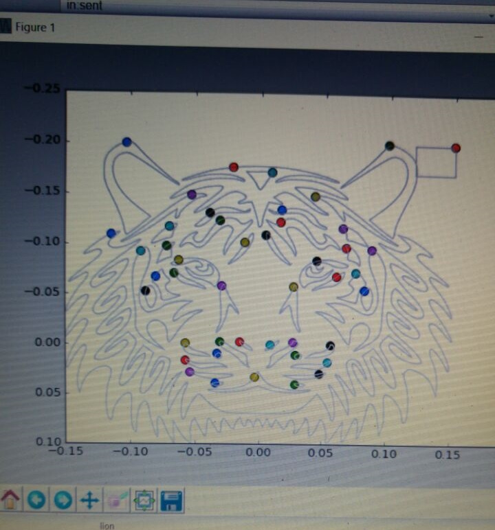
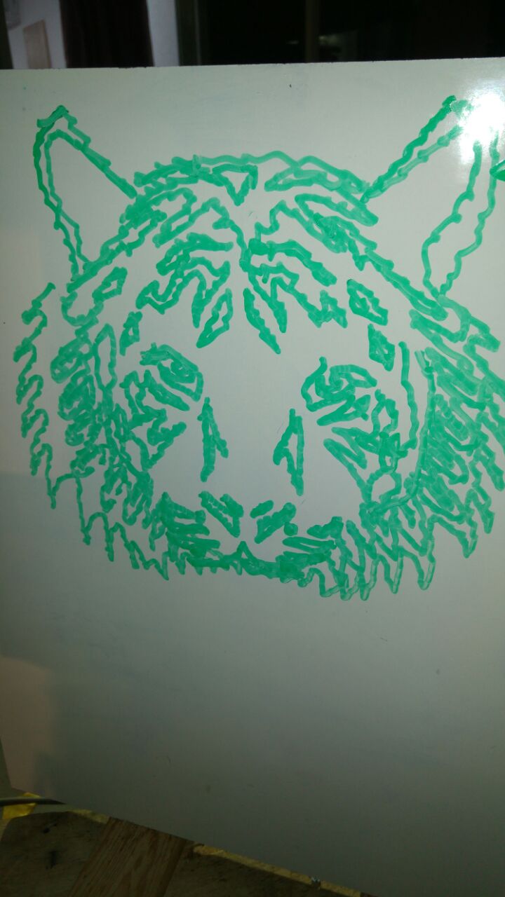
The dots are where a contour starts/finishes and the marker has to be lifted from the board. Then, the file is ready to use in the python script I mentioned above, and this is the result:
To summarize all this part, here's a four minutes video of most of the drawing, not speed up so you can see it yourself working in real-time:
Unfinished Work
There were some more goals we set to ourselves and didn't succeed to finish during Geekcon. Perhaps we will find another time to get together and finish those tasks.
One was our main goal - To make Scorbot draw real people and not just images from the internet. The idea was to take a picture of a person, messed it up a little so it will look funny, posterize it to a black and white image and continue as we've done with the other images. We've started implementing this idea but did not finish, and therefore the code isn't ready to share yet.
Another idea we had, was to draw with more than one color. In the next video you can see we tried to build this apparatus which holds two markers, and when changing the pitch we change also the color. We had to calibrate it a bit, drawing the same image with both colors to see they are getting to the same locations. Eventually we found out it very hard to do this calibration since our apparatus was not very precise. Maybe it will work in the future.
And last, as I explained when describing the PCB part, we must add PWM pins to the drivers to smooth the action Scorbot executes. If you plan to use this design - Take it into account.
Overall we've done a great journey from picking up Scorbot in a junk yard to what it can do today. I've learned a lot about robotics and mechanics during this process, and if you read this post I hope you did as well. If there are any comments, questions or errors in the post let me know in the comment section.
The entire design and code can be found on Github.
AA