Desktop NeoPixel Clock
This project involves building a simple desk clock with NeoPixel rings and a WeMos (ESP8266) processor, which is also a beautiful piece of art.
Previously, I wrote about the LEDs and Buttons Arduino shield which was my first complex PCB Board. Before, the limitations of complicated wiring and my own soldering ability were hard limits. Now that I'm able to design and fabricate my own PCB for a reasonable price, my hobby as a maker has truly opened up. I feel that I can build anything and this blog post is designed to encourage you to do the same
I decided to experiment with NeoPixel rings. I was inspired by these similar projects on Instructables:
I would like to make one for my desk. However, I didn’t like the idea of using laser cut 1/8” plywood , as presented in the first Instructable – this seemed like a lot of work to house such a small object. Since I know how to make PCBs and print 3D enclosures or stands, this would be the best path.
Which Processor Board?
Next, I had to decide which processor to use. It might be easier to use an Arduino Nano, because I have experimented with them in the past and know they are totally compatible with NeoPixels. NeoPixel uses a one-wire like data-protocol on a single Data line with 5v signals.
However, a number of makers have been able to get NeoPixels to work on a 3.3v processor with the Data signal at 3.3v levels.
Therefore, let us try this build this project with an ESP8266 processor. Having a network-attached device is a huge advantage. My fellow maker and WhatIMade.Today blogger MikeD and I collaborated, and decided to build a number of projects based on the ESP8266. Also we would standardize on a specific ESP8266 platform or module.
Here are the top 6 ESP8266 Modules for IOT Projects:
- AdaFruit Feather Huzzah ESP8266
- Knewron SmartWiFi
- NodeMCU Dev Kit
- SparkFun ESP8266 Thing
- Wio Link
- WeMos D1 Mini
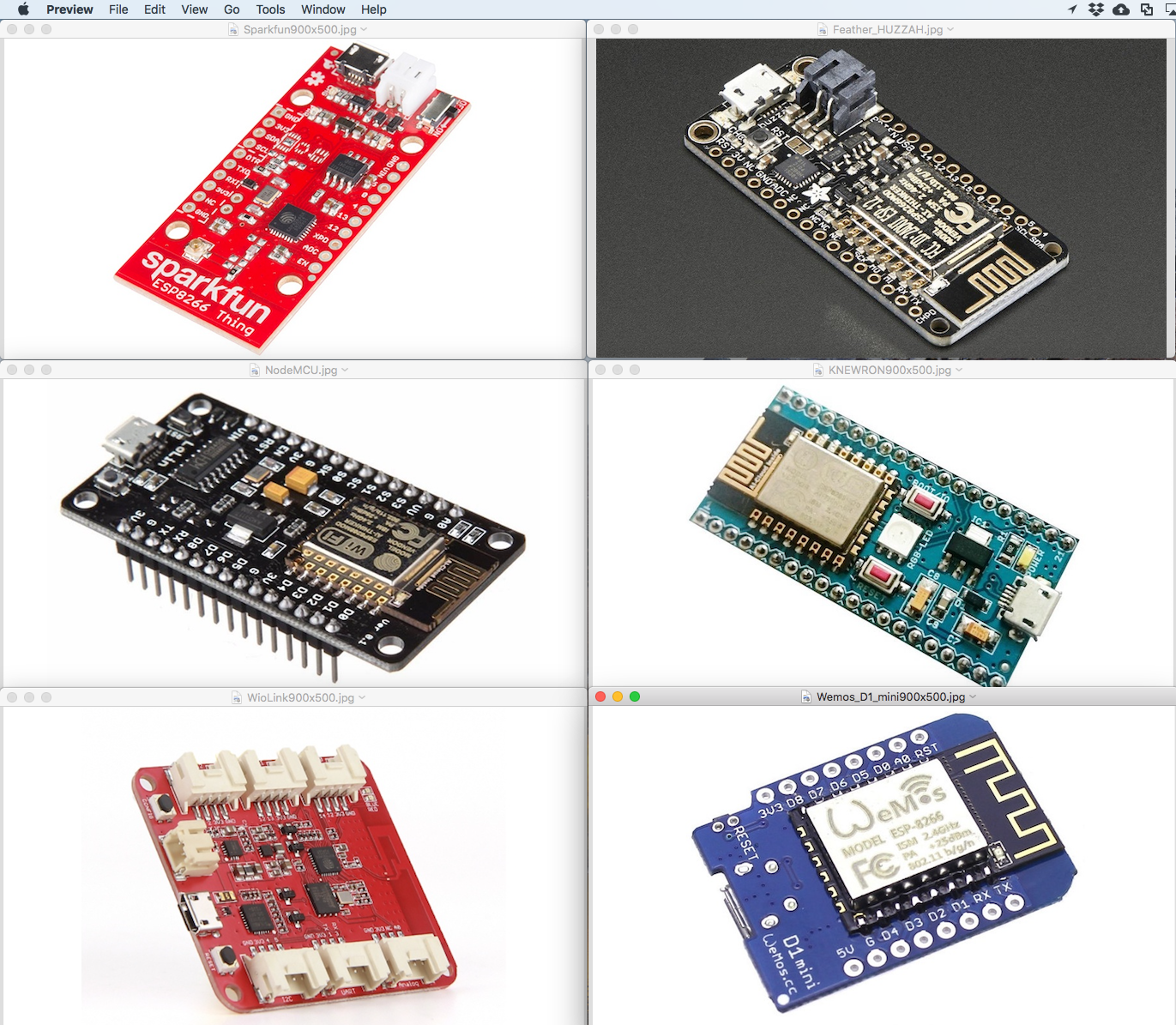
So, which board should we design with? It turns out that all boards work well, are reasonably supported and are usually available. Most importantly, they are all source compatible when using the Arduino IDE.
We chose the WeMos D1 Mini. This board is easily reprogrammable, can be powered from a Micro USB connection, and provides 11 digital I/O pins, while still in a small package.
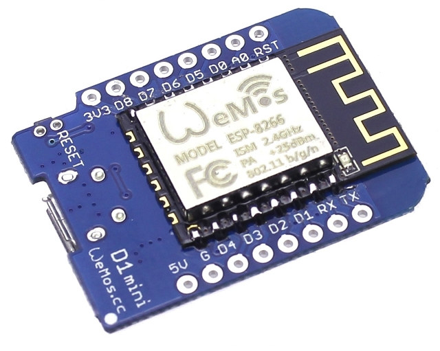
This package is 25.6 mm x 34.2 mm (1.01” x 1.35”), breadboard-friendly, can be either soldered to a PCB or socketed, can be either USB-powered or battery-powered from a 3.5v-6v unregulated source or powered from a 3.3v regulated power source.
The WeMos D1 Mini has several distinct advantages:
- Smallest form-factor in its class for a development board
- Sold from multiple sources and cloned by various China PCB suppliers
- Very cost effective.
The WeMos D1 Mini, along with all the ESP8266-based boards, offers distinct advantages of utilizing a WiFi network connection.
- The device we build can become an IoT device – a network-connected node reporting back to the “Cloud”.
- The device can provide the current date, time even geo-location from the net.
- The device can have a browsable user-interface based on web pages.
- The logic can be significantly more complex, because the underlying processor is an Espressif Systems Tensilica L106 32-bit RISC processor running at 80 Mhz. Also, there is significantly larger code-space and ram space than an Arduino Uno.
A Super-Simple Circuit
Because this is my first experiment with the ESP8266, I wanted to make an extremely simple circuit. No need for a power supply other than the built-in USB connection. No need for a Real Time Clock (RTC); we will get the time over Network Time Protocol (NTP). No need for buttons nor for external connectors.
Here is the simple circuit we designed. First, the “Breadboard” view.
![]()
it is so simple that the breadboard-view doesn’t even need a breadboard! Instead, I prototyped this using these “mini-grabbers” on one side.
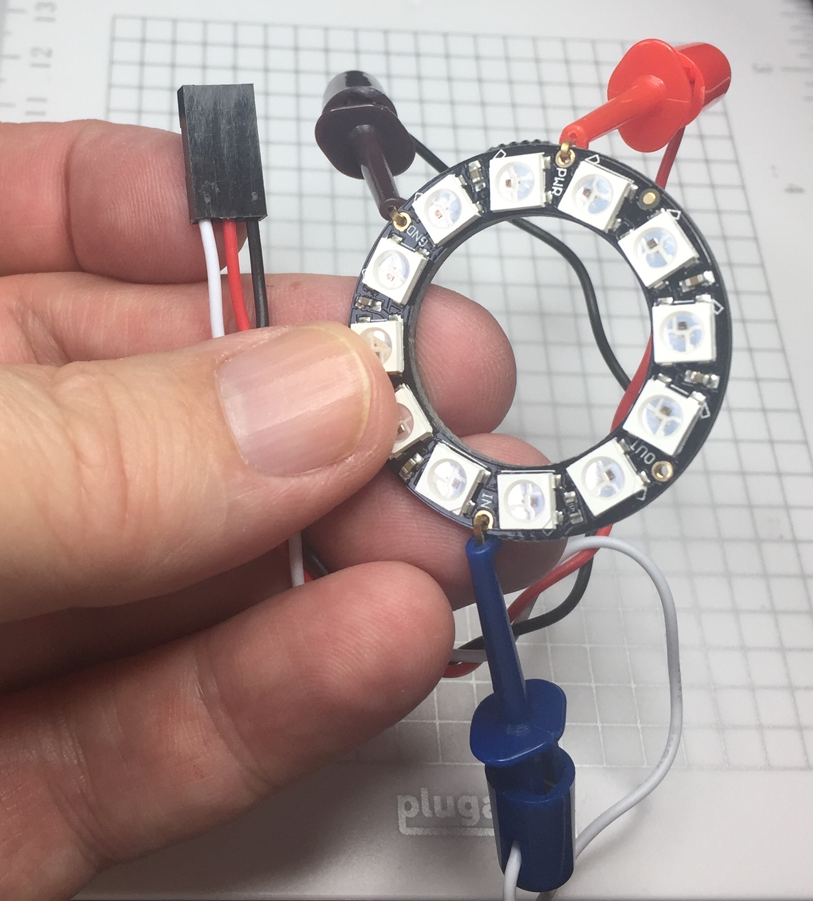
In addition to power and ground, there is only one data signal connected to the WeMos pin D6. Between the two WeMos pixel rings, the DOUT of the first ring gets connected to the DIN of the second. Using this method, the two rings appear as a single 36-LED strand of pixels.
Here is a schematic of this circuit:
![]()
The value of C1 (470µF) and R1 (470Ω) are provided by AdaFruit's NeoPixel Uberguide.
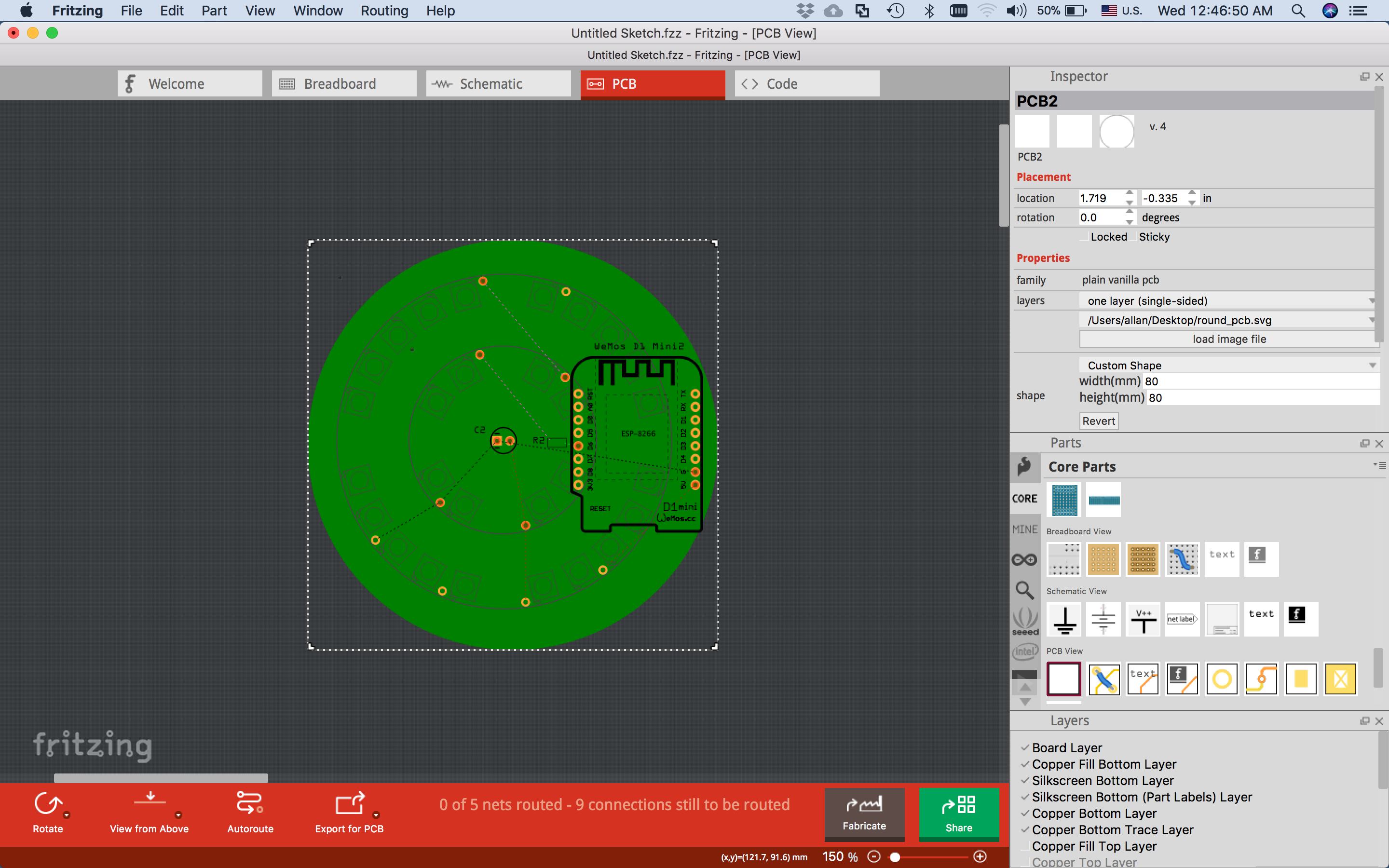
We have already learned how to create a PCB using Fritzing. Here is the PCB View From Above:
![]()
There are two PCB views, the Above and the Below.
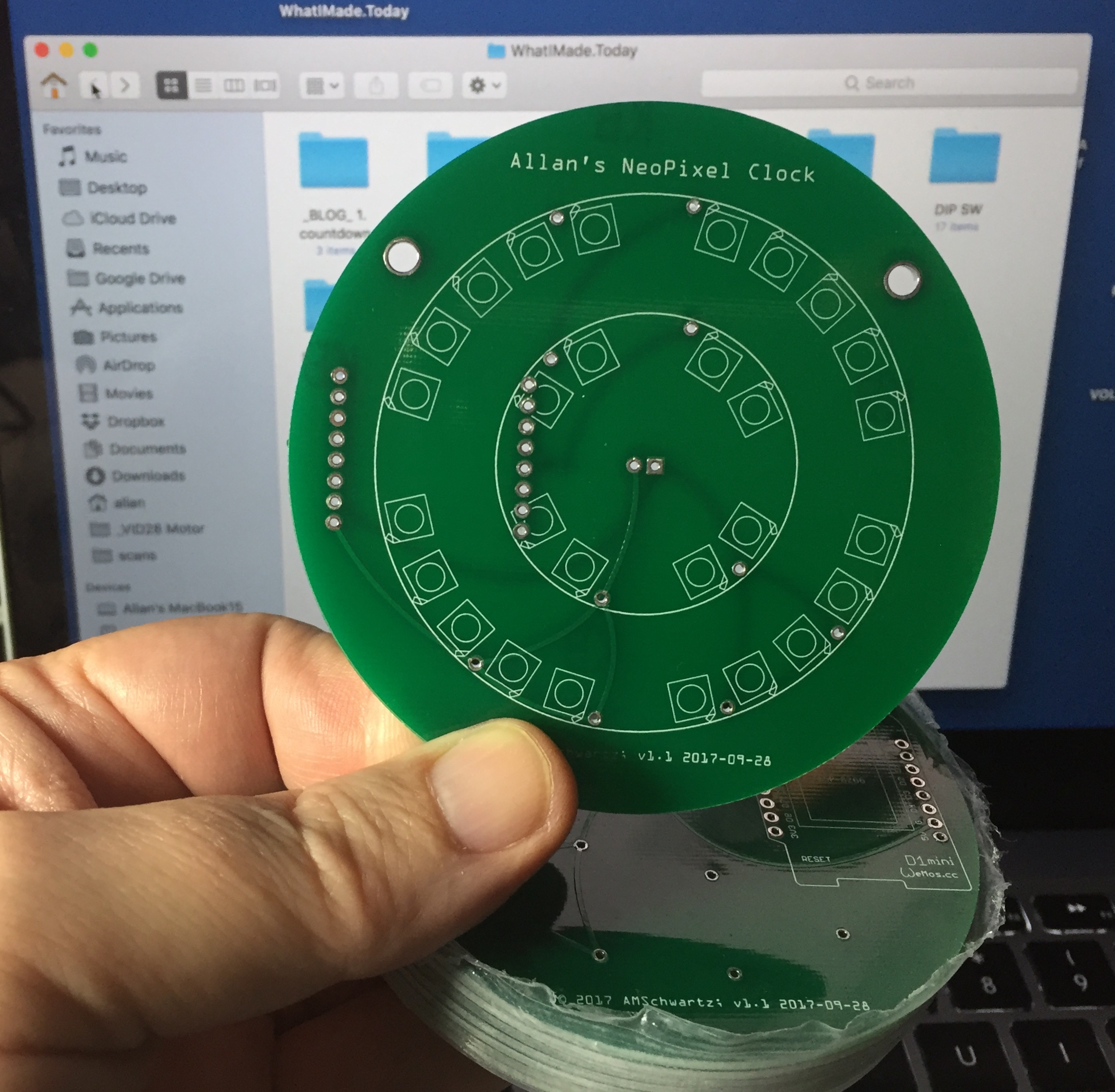
I placed the Wemos processor and nearly all traces on the above side. The View From Below – which contains the NeoPixels rings – is the user-facing side or the clock-face.
![]()
PCB Layout Fritzing Tricks
There are 4 interesting tricks I learned to do with this PCB layout:
- Aligning parts
- Creating a custom board shape
- Creating curved circuit traces
- Drilling holes.
Aligning parts
I made extensive use of the Parts -> Align function, to center the Pixel Rings, and also to place the mounting holes straight.

Creating a custom board shape
I was surprised by how easy it was to create a circular PCB in Fritzing.
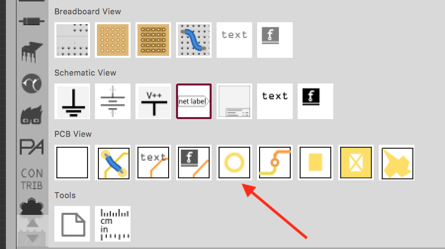
There are two ways to make a circular board:
Click on the PCB board. If one doesn’t exist yet in the PCB View, click in the Parts window, click on Core Parts, then scroll down within that to PCB View. The first icon is for a new PCB. Click on that and drag it to the PCB-View workspace.
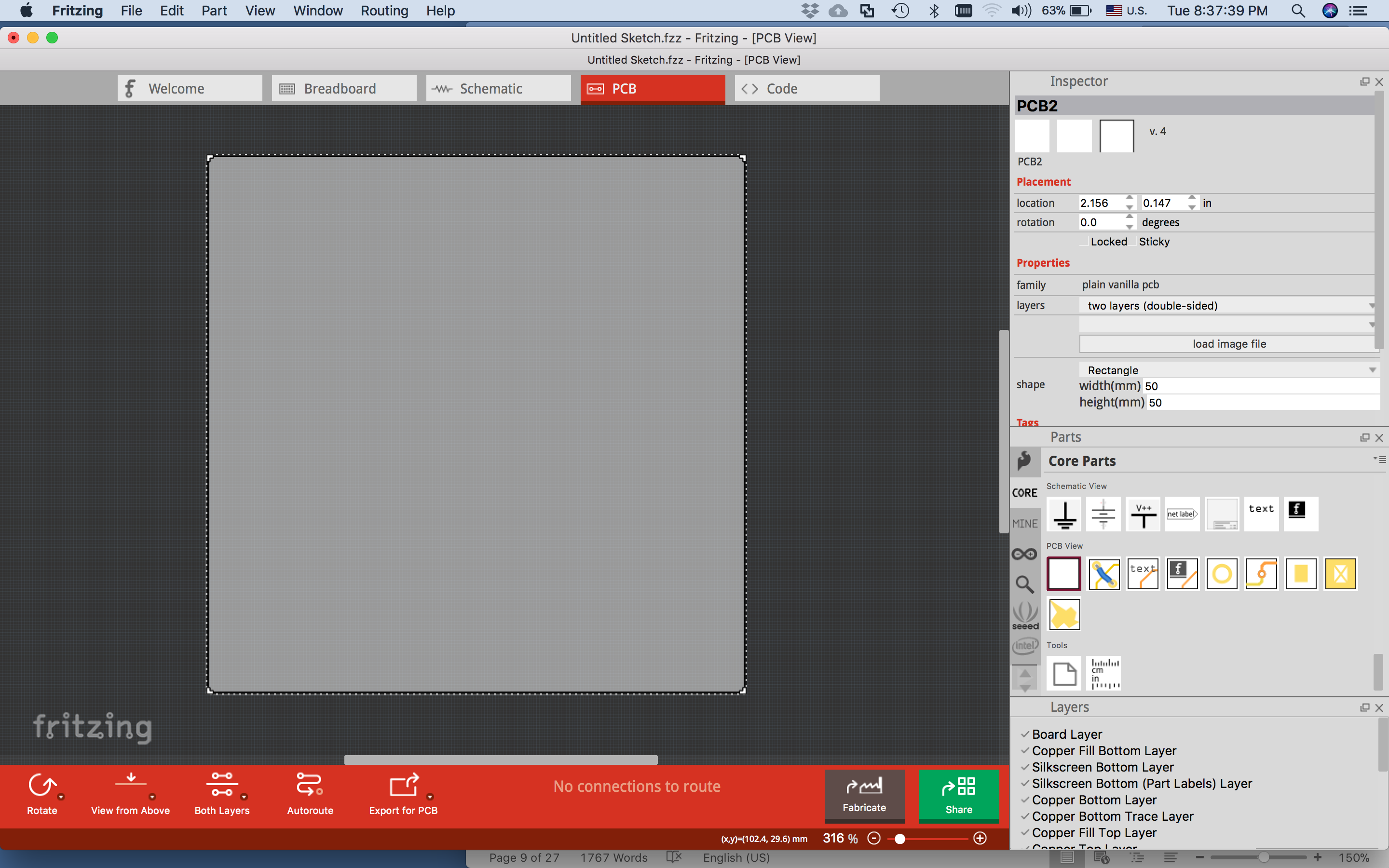
Then, select the PCB, see its properties in the Inspector window (see above).
Select the pull-down under shape Rectangle, and select Ellipse. Set the width and height to the same value (like 80mm). Voila! A circular PCB.
Alternatively, you can design a custom shape in SVG, and download that, clicking on load image file in the Inspector window.
As an example, your SVG file would look like this:
[File contents]:
<?xml version="1.0" encoding="utf-8"?>
<!-- hand coded by Allan Schwartz, Aug 27, 2017  -->
<!DOCTYPE svg PUBLIC "-//W3C//DTD SVG 1.1//EN"
    "http://www.w3.org/Graphics/SVG/1.1/DTD/svg11.dtd">
<svg version="1.1" id="Layer_1"
     xmlns="http://www.w3.org/2000/svg"
     xmlns:xlink="http://www.w3.org/1999/xlink"
     x="0" y="0" width="80" height="80"
     viewBox="-40 -40 80 80" xml:space="preserve">
<!-- User units, in width, height and viewBox are in mm -->
  <g id="board">

    <circle fill="green" stroke="none" stroke-width="0"
        r="40" cx="0" cy="0" />

  </g>
  <g id="silkscreen">
  </g>
</svg>
Then, click on load image file from the object inspector with any PCB selected.
Browse to your file and click OK. You now have a round PCB or any shape that you specify in your SVG. You can play around with location and rotation and width and height, to further scale and translate your PCB object.
The fill color that has been specified in your shape is interpreted by Fritzing as the solder-mask color and is depicted accordingly. Very cool! It would be great if Fritzing had a pull-down selection to depict the standard solder-mask colors for any PCB.
Creating curved circuit traces
Creating curved traces is easier than in most ECAD applications.
Just as in the breadboard mode, you hold down the COMMAND key (on a Mac), and drag the wire to a nice curve shape.
In PCB mode, it is the same – you hold down the COMMAND key and drag the trace into a nice curve shape.
There are some mathematical dependency on the snap-to grid alignment, so if you are in Align to Grid mode (selected under the View menu), the curves are pleasing and reproducible.
Drilling holes
Drilling mounting holes in the corners of the board seems like a very good idea so that you can later put it into a case. We now consider the whole mechanical assembly after building just a few 3D cases. See my earlier blog on that topic: 3D Printing Experience
There is a very convenient hole tool, with settable diameter, and plated pad size.
At one point, I wanted to know how to connect the plated hole to GND, so the signal ground would also be chassis ground. Subsequently, I learned that you don’t want to do that. In fact, you don’t want plated holes as mounting holes. The mounting screws have better “bite” into raw PCB board. In addition, you don’t want to risk fracturing the ground plane by having an over-tightened screw in contact with it.
Here is a table of conventional hole sizes:
| Metric HW | nominal size | ANSI/ASME HW | Drill size |
|---|---|---|---|
| M2 screws | 2mm .078" | 2/56 screws .086" | 2.2mm .087” |
| M3 screws | 3mm .118" | 4/40 screws .112" | 3.2mm .125” |
| M3.5 screws | 3.5mm .138" | 6/32 screws .138" | 3.7mm .146” |
| M4.0 screws | 4mm .157" | 8/32 screws .164" | 4.2mm .165” |
Fritzing has a couple of those sizes built-in and that can be selected by a pull-down in the Object Inspector. It is good to know that cheaper ANSI/ASME sizes can be used with the same hole size as metric screws.
By the way, this simple task of specifying a drilled hole is quite easy in Fritzing, while quite difficult in KiCad (the competing open-source EDA software).
Production
The board is now complete. I exported the Gerber Files, from the File -> Export -> For Production -> Extended Gerber Files
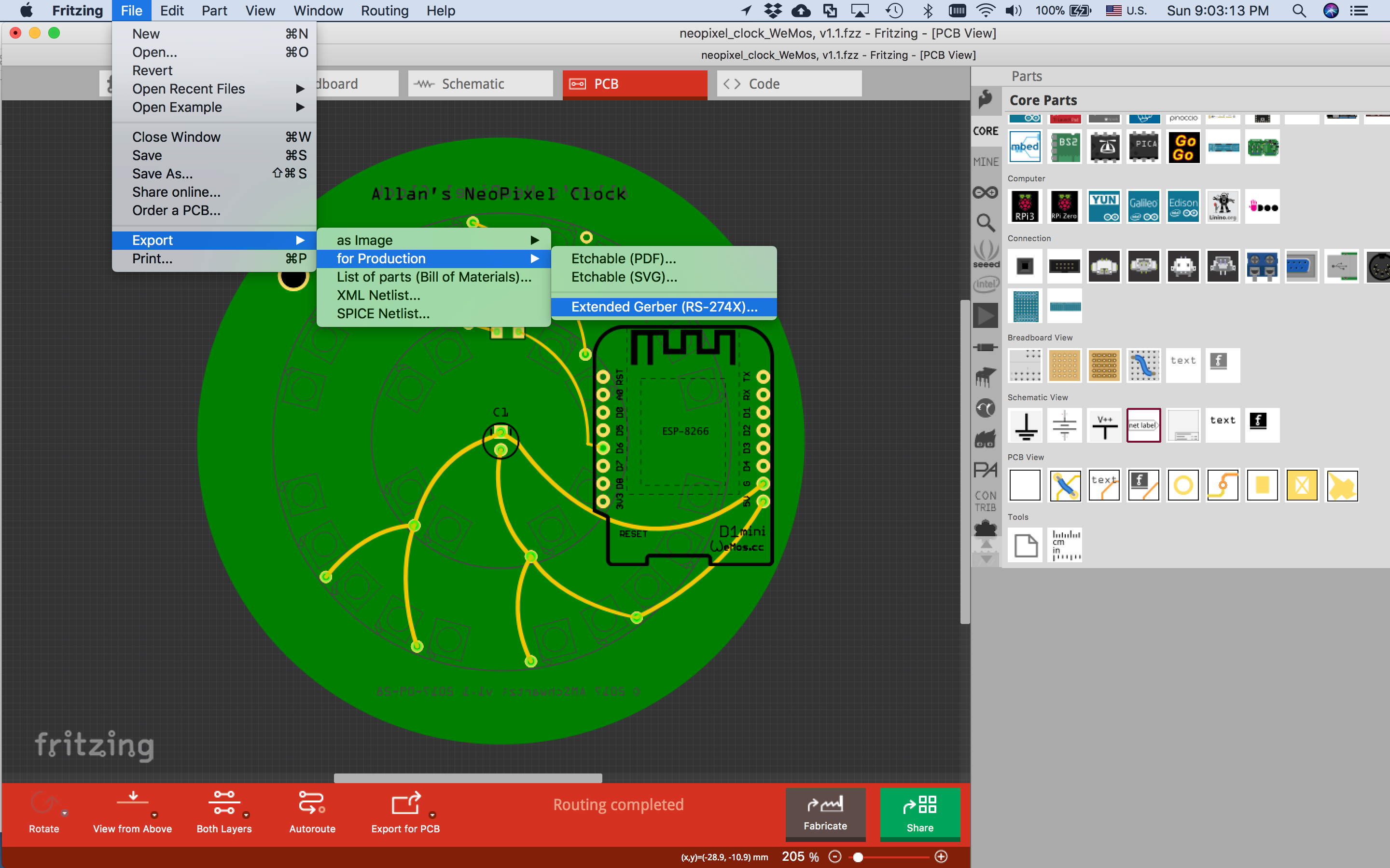
We are now ready to order the PCB fabs. This is my second order of PCBs from PCBWAY, so I submitted 3 board designs to reduce total shipping costs.
The PCBWAY web site has an efficient Fabrication Progress screen:
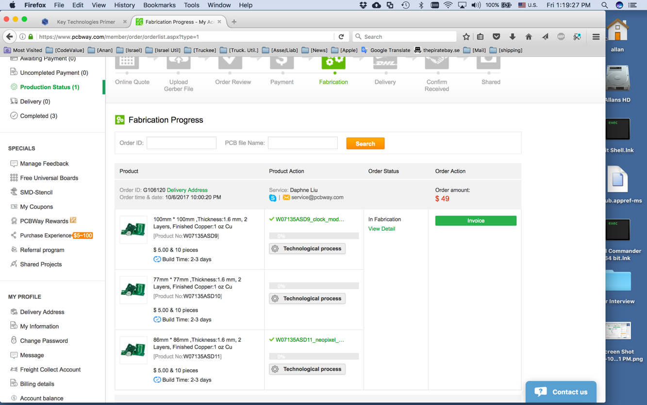
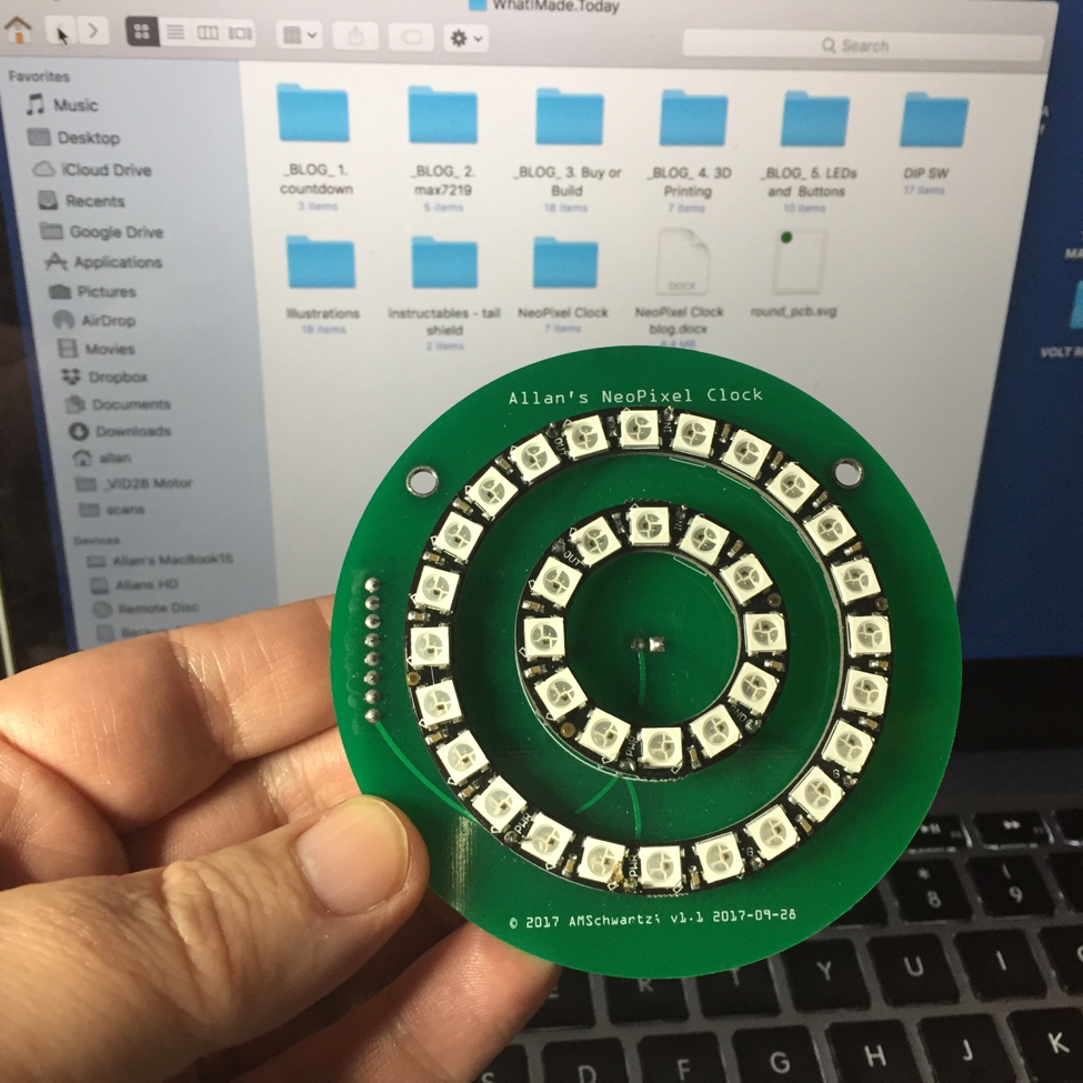
Within in a week, I had the boards in-hand:
There isn't very much to solder. First, the component side -- WeMos on female headers, R1, C1. Then NeoPixel rings are mounted onto single male header pins, then those header pins soldered. Here is my first assembled board:
SOFTWARE EFFORT
Unit Test
The first step is to use one of the example programs AdaFruit distributes with the NeoPixel library. I only had to make a few changes, and the display began to work.
Here are my few lines of changes:
const int NEOPIXEL_PIN = D6;     // WeMos pin D6
const int NEO_NUM_LEDS = 12+24;
const int BRIGHTNESS = 96;       // experiment with this
Adafruit_NeoPixel strip = Adafruit_NeoPixel(
                   NEO_NUM_LEDS,
                   NEOPIXEL_PIN,
                   NEO_GRB + NEO_KHZ800);
However, that was just a Unit Test of the hardware.
Clock Application
The next task will be to try to use this as a clock.
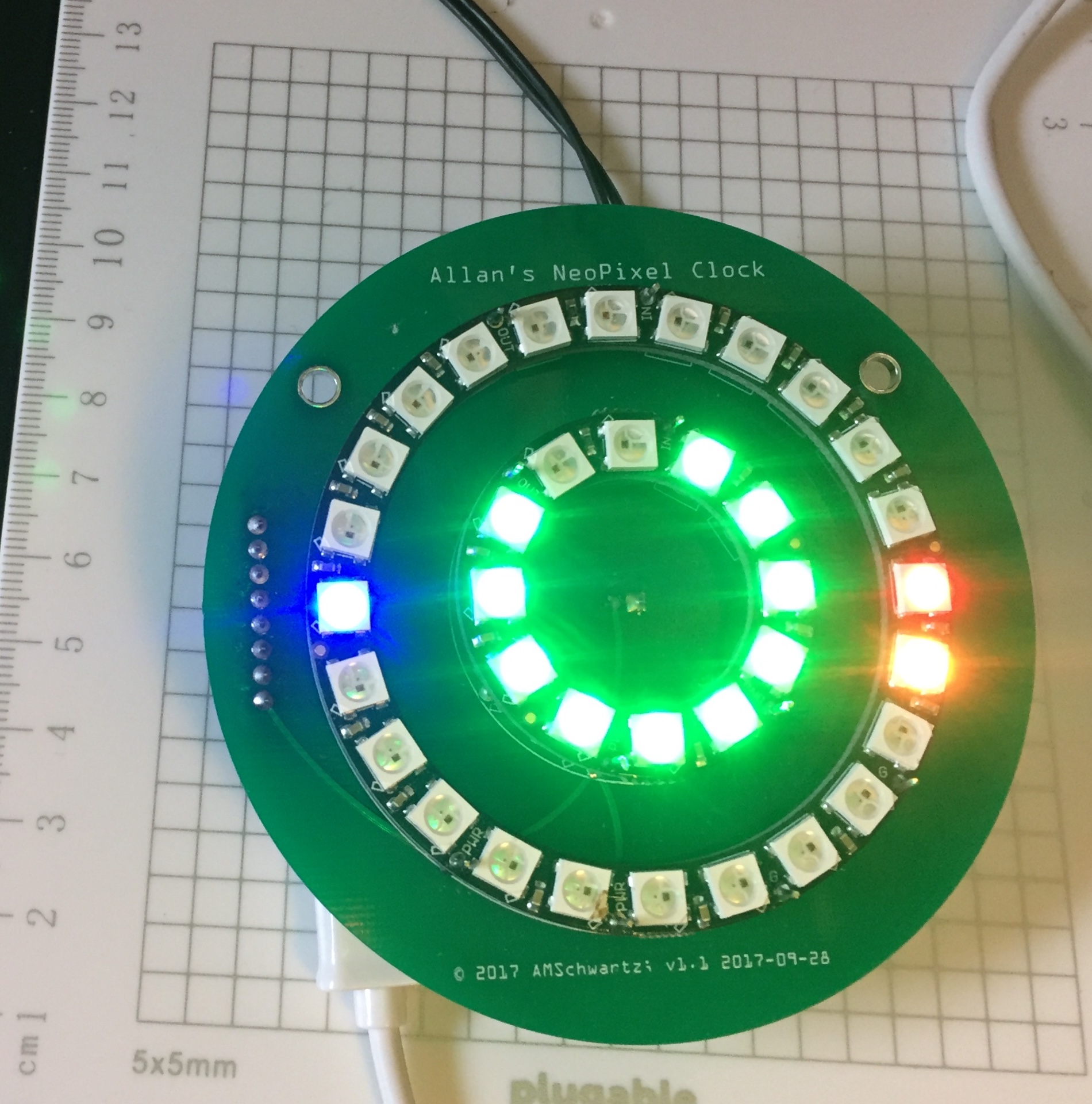
Let’s specify how to represent time using 36 NeoPixels.
Minutes are indicated on the outer ring. The minutes are rounded to the closest 2½ minutes -- because we only have 24 pixels in that ring – and displayed in two pixels using colors red and orange. Red indicates the closest 2½ minutes, and orange represents a delta of one more minute.
Hours are indicated on the inner pixel ring in Green. I also thought about changing this color at sunrise and sunset, but I haven’t implemented this yet.
Seconds are indicated by a single Blue pixel traveling around the outer and larger pixel ring.
At every minute, there is a minor animation at the exact 1-minute. I also thought about indicated the outside temperature at the 1-minute interval. I haven’t implemented this yet, either.
Here is a photo taken at 10:16:45.
How the networked-time function works
One of the more interesting parts of the code is the function getTime_from_NIST(), which retrieves the current time from the nist.time.gov NTP servers. There are a lot of examples that I have seen on the Web of how to connect to NIST.
Some use the UDP protocol. I think that is a poor idea because the UDP protocol is unreliable; therefore one needs complex mechanisms in the code to manage retries.
Some use the http protocol. An exceptionally clear explanation of http connection-based code is here:
https://diyprojects.io/esp8266-web-client-tcp-ip-communication-examples-esp8266wifi-esp866httpclient/#.Wg6iMoZx2L4
However, it is slightly more complex than it needs to be. I opted to use simply TCP -- open a TCP socket to a NIST server, read a packet, it contains the date&time in ASCII, close the socket. Done. Simple.
To see what I am describing, you can perform this protocol entirely from a Terminal window, using the nc (netcat) command. The nc command opens a TCP socket and writes and reads from it.
Type the following command
nc time.nist.gov 13
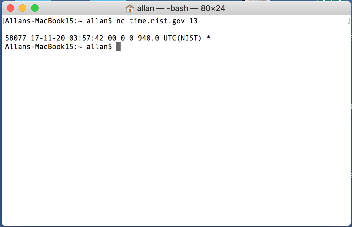
We have received back the result
17-11-20 03:57:42
This is exactly what we want our code to do. Here is the Arduino function to do just that:
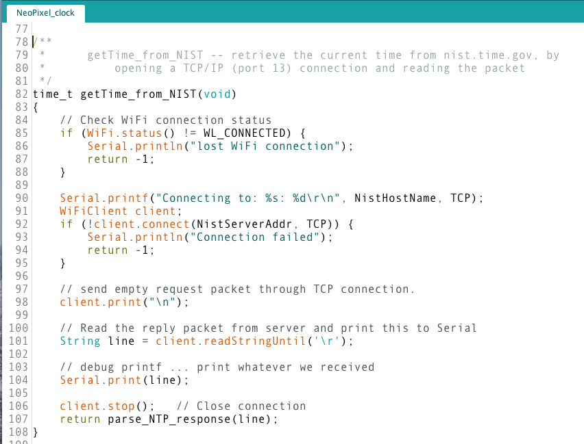
In the above code, we
- create a
WiFiClientobject (an abstraction for a TCP/IP stream) - connect to a TCP/IP socket at the given server IP address/port
- send an empty request packet
- call
readStringUntil(‘\r’)which reads the response line. This method works on any object class that behaves like a stream object. - close the TCP/IP stream.
Finally, we parse the one-line response received, and return with the date/time value.
Other interesting points of the code
There are a few other interesting points related to the code that stand out.
First of all, we treat the two NeoPixel rings as one continuous strand of NeoPixels within the code, because that is how we have wired it up. The code updates all the NeoPixels exactly once a second.
Time Management.
I have simplified time-management. The function synchronizeTime() stores the time_t variable clocktime_s, representing the time on the clock, as retrieved from the NIST timeserver. Plus using the local millis() timer, stores the clock_t system clock at the moment of synchronization.
Notice that type time_t and type clock_t are completely different. Each variable that holds a time is either a time_t or a clock_t. In addition, the time_t variables end in _s and clock_t variables end in _ms, indicated their units (seconds or milliseconds). This is a modified Hungarian Notation, which many professional embedded programmers use to clearly indicate type or units or scope of each variable.
Later, in function timekeeping() – called once per second – we set global time variables to reflect the current time. Then we call function refreshClock() to update the NeoPixel rings.
ARDUINO CODE LISTING
I have committed all the code to my GitHub account.
You can view the Arduino C code here:
NeoPixel_clock.ino
You can download the Fritzing project here:
neopixel_clock_WeMos, v1.1.fzz
Functioning device
Here is a video of the code working:
[you tube video] forthcoming
Conclusion
- This was a fun little project to build.
- Fritzing continues to delight me, especially with how easy it is to create PCBs, with excellent results and with good documentation.
- PCBWAY continues to satisfy me as a PCB vendor.
- NeoPixels are fun to play with and you can make entertaining displays quite easily.