3D Printing an Enclosure – Finishing an Arduino Project in Style
Our latest toy is an MP Select Mini 3D printer. I purchased this with fellow Maker and whatimade.today associate Michael Diamond. We selected this entry level printer that came preassembled, easy to operate and inexpensive. The Amazon.com price for an MP Select Mini 3D Printer was just too good to pass up – about $220. I’ve spent more on a soldering iron in the past!
Mike and I have been busy printing lots of gadgets, toys, Raspberry Pi and Arduino enclosures and geared objects. We are having a ball! Designing and printing 3D objects is so much fun.
Today, I am telling you about my own 3D-printing experiences.
Finishing an Arduino Project – 3D Printing an Enclosure
My first practical device to print was an Arduino enclosure. This allowed me to complete a previously-built Arduino Project, the Time/Date/Temperature display device, previously blogged about. This uses a multi-digit 7-segment display.
The enclosure is comprised of two pieces, an enclosure back, and an enclosure front with cutouts and mounting holes for the 3 subassemblies:
- An Arduino Nano
- The 8-digit 7-segment display
- The RTC / Temperature module
Each subassembly will be attached to the enclosure front. To build this enclosure, I followed these steps:
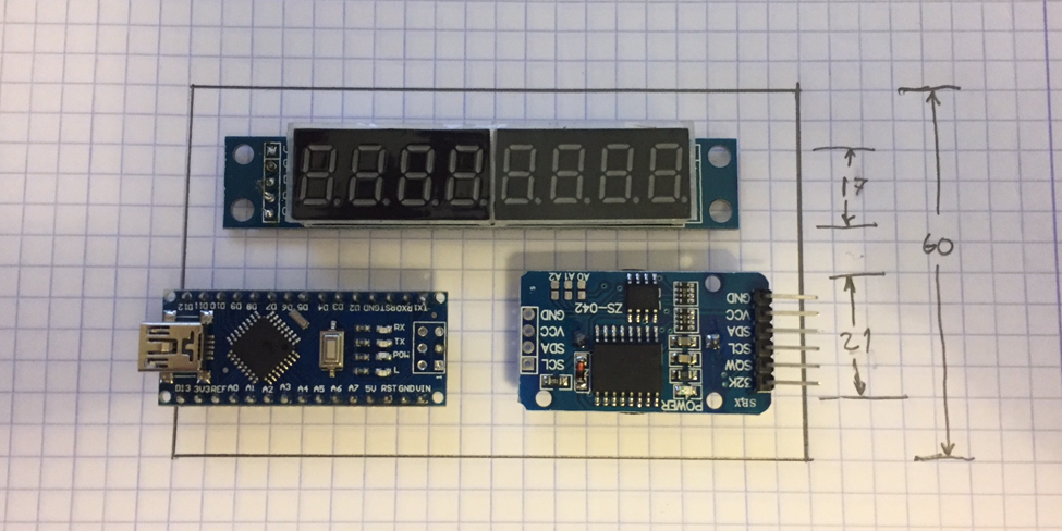
First, I imagined the enclosure, sized to fit the three subassemblies:
| Item | Overall Size | Cutout size | Mounting holes |
|---|---|---|---|
| Arduino Nano | 43 mm x 17 mm | button/leds:19 x 13 Power plug: 10 x 7 |
none |
| 8-digit display | 82 mm x 15 mm | 63 mm x 16 mm | 4 mm |
| RTC module | 38 mm x 21 mm | 19 mm x 21 mm | 2.5 mm |
The cutout above the RTC module is so the temperature sensor chip is exposed to room air. The cutout above the Arduino Nano is so we can see the power/Rx/Tx LEDs and have access to the reset button. However, I now see that that is superfluous, and I might change those to smaller ventilation holes in my next version.
About 10 mm of space was left between all components. If I had wanted a tight fit around the components, then I would leave 1 mm of space around all components. However, in this application, I want space for wiring and space for the components to breathe! From these dimensions, we can see that we need an overall enclosure size of 100mm x 60mm.
Tinkercad
There are a number of different programs one can use for 3D design. Mike and I are using Autodesk’s Tinkercad, which is an easy and free version of the well acclaimed Autodesk Fusion 360 program. The advantages of Tinkercad are:
- It’s cloud-based, accessible by your browser
- It’s easy to learn and use
- Large 3D printer userbase
- Plenty of tutorials on YouTube
- You can share your designs and tinker with other makers’ designs
- It’s free
Getting Started
Its quite easy to get started. Go to www.tinkercad.com. Clink on SIGN UP and create your account. Click on LEARN and follow the brief lessons. You can jump in and start designing right away.
Creating the Enclosure Front
We create the Enclosure Front in Tinkercad as follows:
- Open up a new workspace by clicking CREATE NEW DESIGN.
- Select a Box and Lid object from the Featured Shape Generators palette. Drag it onto the Workplane.
- Specify the
Box Length 100,Width 60,Height 10, andBox Topin the Shape customizer window. - Begin making the rectangular cutouts. (There was a lesson on cutouts in the tutorial). Because the box top is face down on the drawing plane, you actually have to imagine all the boards upside down and mirrored (left to right). This is a fun challenge.
- Make cutouts as appropriate for the 3 boards.
- Make standoffs appropriate for the Nano and the RTC board.
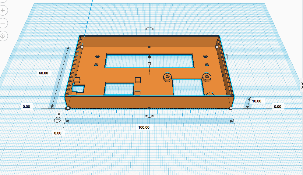
- Virtually drill mounting holes
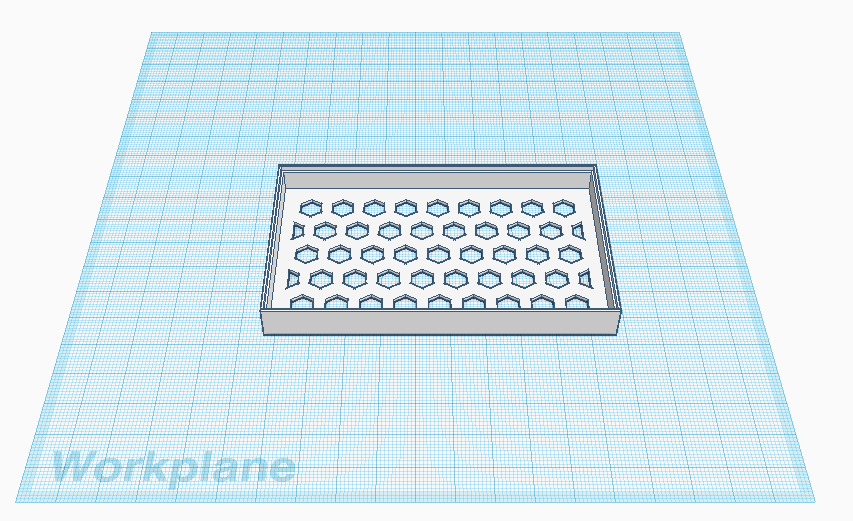
- The design should look something like this:
Feel free to download my design. Although, it will probably have to be customized based on the size of your components.
Finally print this object, the Enclosure Front. I used the standard settings for PLA:
- Layer height 0.15 mm
- default shell thickness, top/bottom thickness
- Fill density 20%
- default print speed
- Printing Temperature 200° C
Here is a picture of my test print, done with a print-fineness of 0.3mm, so it can be done quickly.
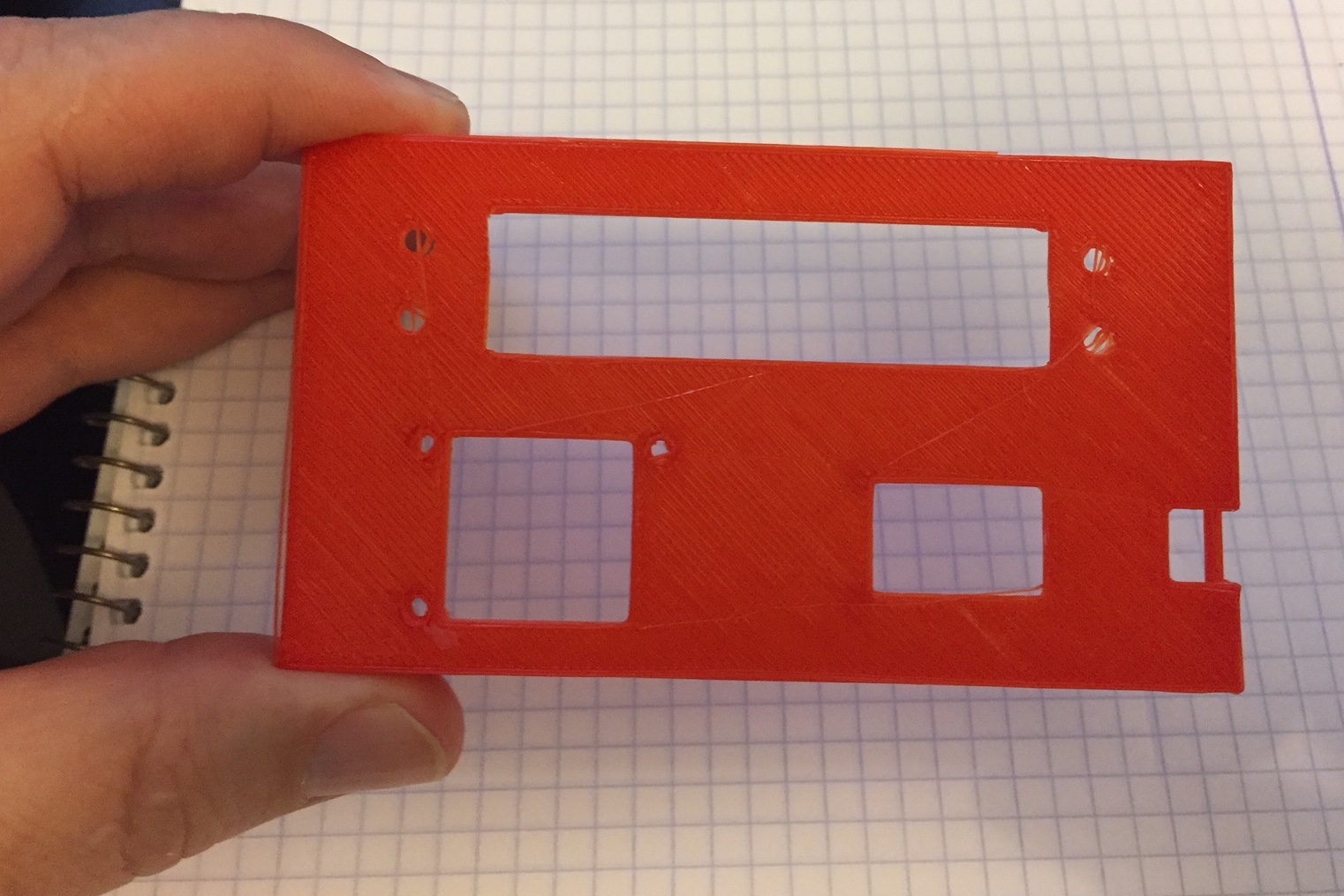
We make a few small modifications to the model and printed the final object at a print-fineness of 0.15mm.
The Enclosure Back
Next we need the enclosure back.
We design the Enclosure Back in Tinkercad as follows
- Open up a new workspace by clicking CREATE NEW DESIGN.
- Select a Box and Lid object from the Featured Shape Generators palette. Drag it onto the Workplane.
- Specify the
Box Length 100,width 60,Height 10, andBox Bottomin the Shape customizer window. - Make cutouts for air holes. I did this by selecting the Honeycomb object from the Featured Shape Generators palette and dragging it onto the Workplane.
- I customized it as follows:
Hole(anti-matter),Radius 4,Rows 5,Columns 9,Minimal Thickness 2. - Align the honeycomb pattern, with the Box Bottom, then Group to virtually drill these holes.
- Save
Feel free to download my design.
Finally print this object, the Enclosure Back. I used the standard settings for PLA:
- Layer height 0.15 mm
- default shell thickness, top/bottom thickness
- Fill density 20%
- default print speed
- Printing Temperature 200° C
Here is the printed back:
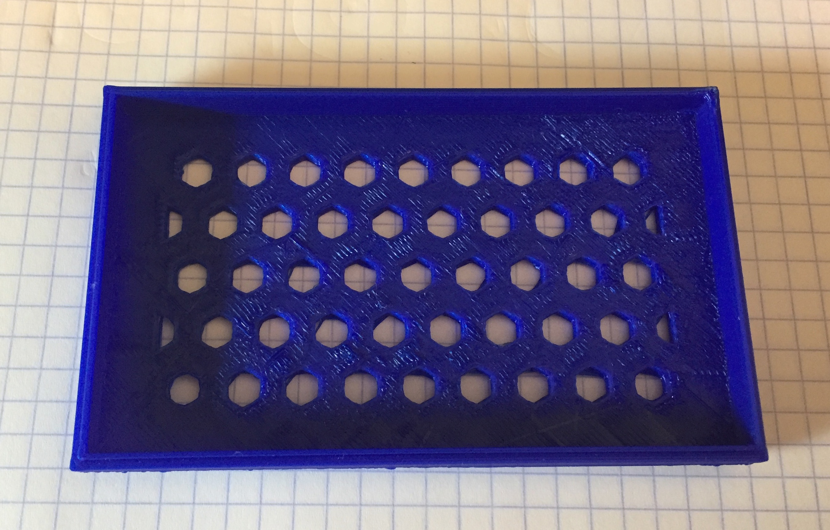
As you can see, we have some surface-quality issues to work out. Mike and I are working on that. This might be because we need a different build plate temperature. Or the nozzle temperature isn't optimal. Or the room humidity (greater than 90%) is too high. Or the adhesion to the print bed isn't perfect. We are working on this, with guidance from sites such a all3dp.com.
Project Assembly
Now, it’s time to assemble. With this technique, the boards are not attached to a PCB but directly to the enclosure. You have to remove (desolder) all of the headers and side connectors.
To remove an unwanted header pin is to set your soldering iron on high (400° C) and then heat up the pin. Then gently pull out the pin with needle-nose pliers. This may leave the pinhole blocked with solder. If you need that pinhole clear, use either a mechanical solder-sucker, or a copper braid solder-wick to pull out the molten solder.
Once the boards are clean of unwanted pins, its time to preassemble. Place the RTC board and the 8-digit display in this enclosure. Attach with 3mm x 8 and 2.5mm x 8mm machine screws.
Prewire the Arduino outside of the enclosure, solder the 5 wires for the Display connection and the 4 wires for the RTC connection – just on the Arduino.
| Signal Name | Arduino | 7-segment Display |
|---|---|---|
| +5V | VCC | |
| GND | GND | |
| DIN | D4 | DIN |
| CS | D5 | CS |
| CLK | D6 | CLK |
| Signal Name | Arduino | RTC Module |
| +5V | VCC | |
| GND | GND | |
| SDA | SCL/A4 | SDA |
| SCL | SCL/A5 | SCL |
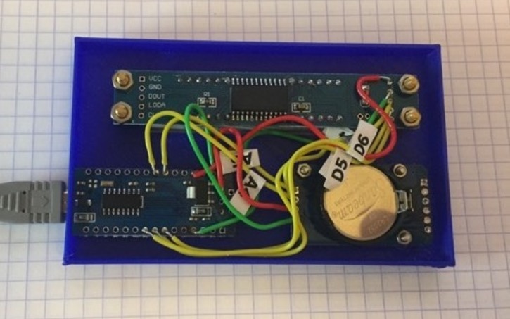
It’s a good idea to label all data wires and color coded all power and ground wires, as I have done in the photo below.
Insert the Arduino Nano. Now solder the wires to the RTC module, then the Display module.
After the entire assembly is functioning as designed, the Nano can be hot-glued into position on mounting tabs in each corner.
I had to wire this project three times. Once with stranded wires but that didn’t work out.
The second time with 24gauge solid-core wire but the wires were trimmed too short.
The third time with 24gauge wire, pre-cut and pre-stripped, was the charm:
Arduino hacking
Next, we adapt and test the Arduino code:
In this case, I copied the code from my pre-existing project. I made some small port-assignment changes, just for the convenience of wiring.
In addition, I made one rather interesting improvement. The RTC is automatically set from the compile time of the Arduino code. This is possible because the Mac Book I am running the Arduino IDE on has the accurate and correct time and the process of Upload recompiles the code. The compile time constants of __TIME__ and __DATE__ are set by the compiler and accessible from your code. Here is the code:
// ... set the RTC date and Time to the compile date and time
void set_RTC_to_compile_time()
{
    const char time_now[] = __TIME__;   // hh:mm:ss

    Serial.print("compile time: "); Serial.println(time_now);
    int hh = atoi(&time_now[0]);
    int mm = atoi(&time_now[3]);
    int ss = atoi(&time_now[6]);
    Serial.println("hh: " + String(hh) + " mm: " + String(mm) + " ss: " + String(ss));
    rtc.setTime(hh, mm, ss);        // Set the time to the compile time (24hr format)

    const char date_now[] = __DATE__;   // Mmm dd yyyy
    const char *months[] = {"Jan", "Feb", "Mar", "Apr", "May", "Jun",
                            "Jul", "Aug", "Sep", "Oct", "Nov", "Dec" };

    Serial.print("compile date: "); Serial.println(date_now);
    int Mmm = 0;
    for ( int i = 0; i < 12; i++ ) {
        if (strncmp(date_now, months[i], 3) == 0 ) {
            Mmm = i + 1;
            break;
        }
    }

    int dd = atoi(&date_now[3]);
    int yyyy = atoi(&date_now[7]);
    Serial.println("Mmm: " + String(Mmm) + " dd: " + String(dd) + " yyyy: " + String(yyyy));
    rtc.setDate(dd, Mmm, yyyy);     // Set the date to dd-Mmm-yyyy
    rtc.setDOW();                   // Calculate and set Day-of-Week
}
You can download all of the code from here:
My GitHub repository.
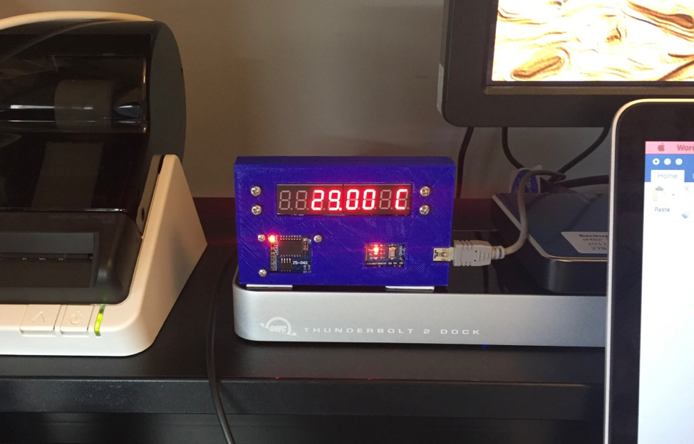
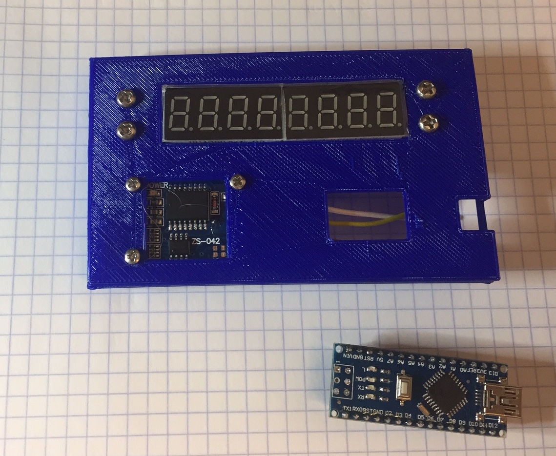
Once the code is working as desired, you have should have something that looks like this:
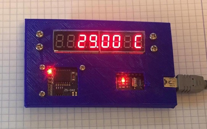
Then attach the enclosure back to the enclosure front -- it’s an interference fit. It's not quite tight enough, so I used some scotch tape to hold it together.
Here is the finished device placed on my desk -- Voila!