For nearly 10 years I've had a large hourglass sitting on my desk. It has fine sand that takes exactly 30 minutes to drop through from one end to the other.
It looks something like this.

I bought it long before I became involved in the Maker World and I've often wondered how I've managed to preserve it for so many years without smashing its delicate glass.
As my knowledge of "Making" developed, I discovered stepper motors and how to control them with a simple Arduino sketch.
One day, while fiddling with my hourglass, I thought, "wouldn't it great if I could make a device that inverted it automatically every 30 minutes?"
That's when this quest began.
No Workshop
I don't have a true workshop. I have a few tools, but no drill press, no circular saw, no lathes or metal-working equipment, or indeed anything that allows me to take wood or metal and hone it to shape. Unlike many readers, I don't have huge hardware stores either, having to make do with bits and pieces I find lying around. I usually find some flimsy plastic, or popsicle sticks that let me construct shaky models with a hot glue gun.
Constructing an hour glass inverter with no workshop was to be quite a challenge.
The Stages
I needed:
- To grasp the neck of the hourglass firmly without breaking it.
- A bar attached to the neck that allows you to pivot the hourglass.
- Supports on each side of the horizontal bar.
- A stepper motor to turn the hourglass in a controlled fashion every defined period.
- A controller for the stepper motor.
- A sketch for the controller.
- A way for the motor to rotate the hourglass. (This turned out to be the hardest part of all.)
First Attempt
This was my first pathetic attempt. (I was so appalled by it, I put it on "shittyrobot" subreddit and not one single person upvoted it!)
As you can see, I used popsicle sticks for the entire construction. Notice the following:
- I grasped the neck of the hourglass with two pipe brackets, and a rubber door stop sandwiched between them to complete the grip.
- I used hot glue and zip ties to connect the pipe brackets to the horizontal bars.
- Supports and horizontal bars are made of popsicle sticks.
- Note the motor. It's a NEMA 17 stepper. More about that below.
- The inversion is done by spooling string on the motor shaft. A popsicle stick is attached to the horizontal bar as a lever for the string to pull on. (Of course, this will only work once. When the sand flows to the bottom, turning the motor to release the string won't turn the hourglass back!)
I put a lot of hours into it and it was an abject failure. I took it apart so that nobody could see my dreadful work and put the hourglass back on my desk to torment me for the next few months.
The Motor
In fact, I'd originally tried a simple BYJ48 stepper. I attached the motor's shaft straight on the horizontal support bar but there wasn't enough torque in the motor to lift the weight of the sand. That's why I went for the NEMA 17 instead. As it turns out, this was the beginning of a fascinating learning process.
The Monoprice Select Mini V1 3D Printer
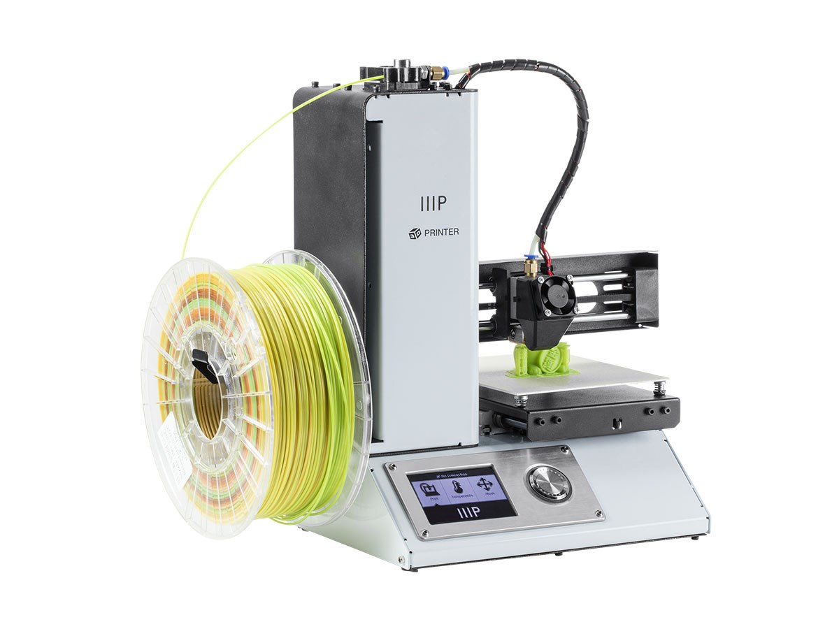
When I finally acquired a 3D printer one of my first projects - after I'd learned a bit of CAD and PLA printing - was to get my Hourglass Inverter up and running.
Lets take a look again at the list of stages above:
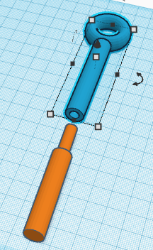
- Using Tinkercad, I created a neck gripper with the perfect diameter to grasp the center of my hourglass. To the neck gripper, I attached horizontal bars.
- For the supports, I created this:
 The problem was, the Monoprice only prints to a maximum of 120 mm. My support needed to be twice that. I got around it by making the bottom of the support hollow, into which I slotted this:
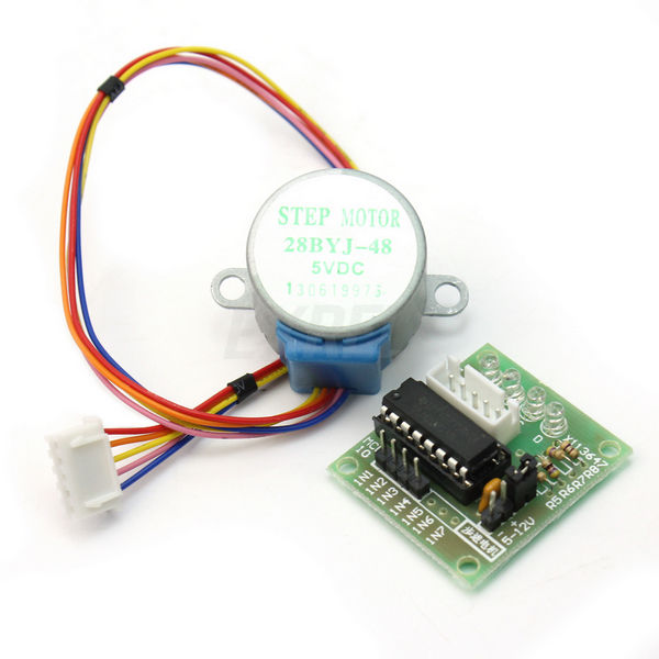
- I didn't want to waste a NEMA 17 on such a light job and I was determined to use the small BYJ48 motor. This is where things got really interesting.
Pulleys and Gears
I knew it's possible with gears and pulleys to use a low-torque motor to lift a relatively heavy weight. All I needed was to understand the principles and produce the gears. A quick glance at YouTube and I discovered how a gear train can dramatically increase the effectiveness of a motor.
Off I went to Tinkercad to create my gears - which turned out to be much harder than I thought. Yes, plenty of gears exist for downloading, but I wanted a 1:6 ratio. That meant I needed to take an existing gear and make a larger one with six times the number of teeth.
Anyone who has used Tinkercad knows that when you increase the scale of something, the whole object changes size - including the teeth. So, my enlarged gear had the same number of teeth as the smaller one, and each tooth was far too big. Not much use for anything.
There are gear generators for this type of thing but I couldn't get them to do what I wanted.
Let's Try a Pulley
Having wasted a few hours on gears, I decided to try a pulley instead. It's basically the same principle. A small pulley attached to a large one can also "magnify" the torque.
I produced two pulleys on Tinkercad.
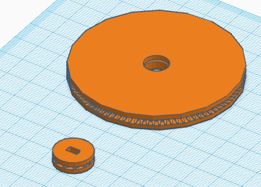
If you look closely you'll see that they are two disks, one on top of the other, with ridges between them. The idea was to create friction so that the string between them wouldn't slip.
Getting a pulley to work needs a bit of distance between the upper and lower pulley, so I planned the large one attached to the horizontal bars of my hourglass, and the smaller one on the motor at the base.
It didn't work. Not only was it difficult to get tension on the string between the pulleys, but it kept slipping despite my friction ridges.
Back to the Gears
So then I spent many hours experimenting with gears designs.
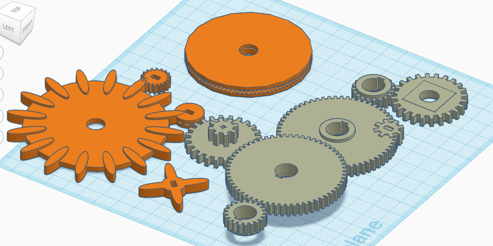
Let's look at this photo:
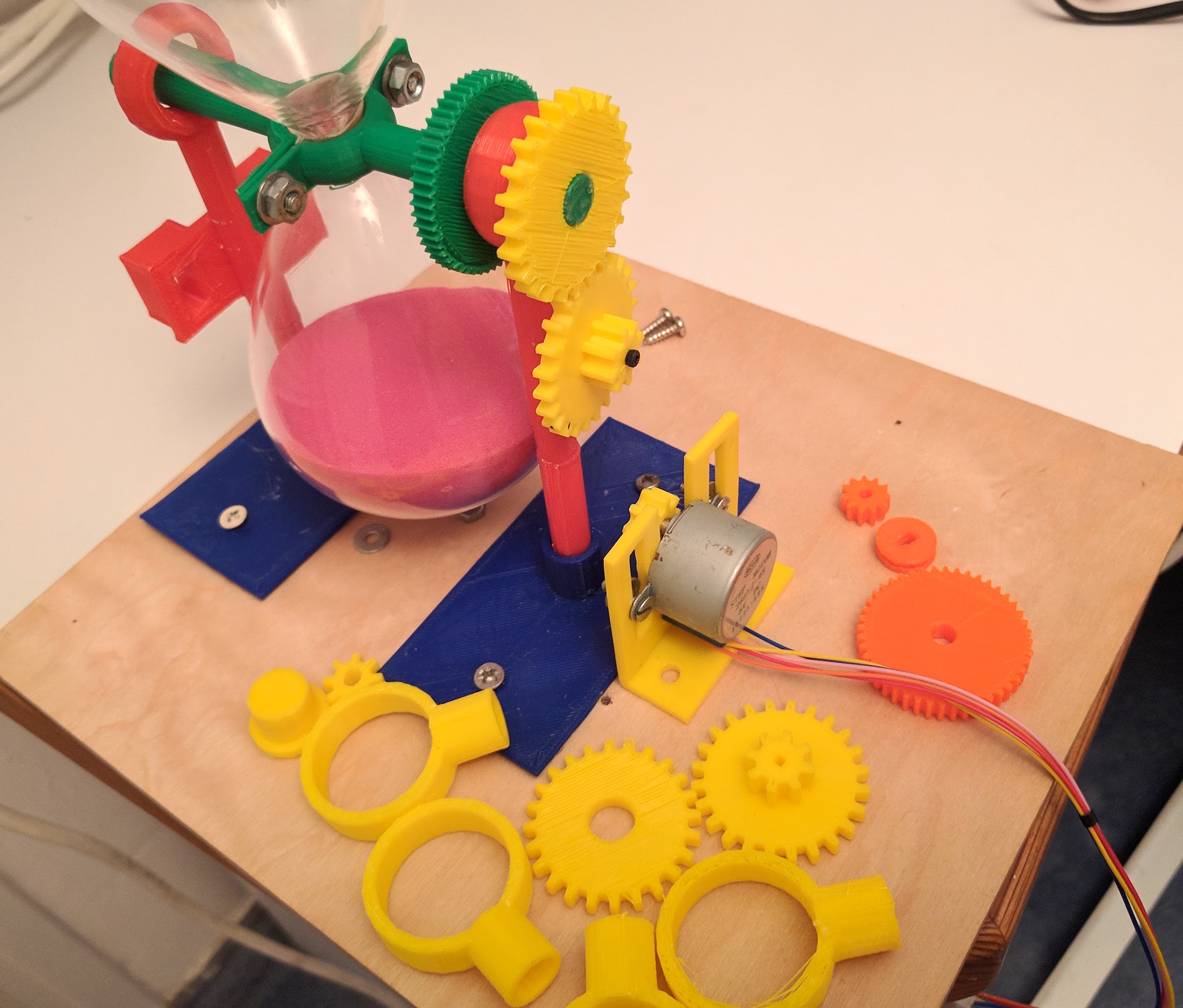
At this stage, I was still set on creating a gear train that was going to transfer torque from the motor on the base up through gears to the horizontal bar. I tried several variations but couldn't get the gear train to rotate smoothly. The gears would stick - probably because I couldn't get them tight enough against their support, while allowing them to rotate freely.
Before I continue, there are another few things to note in this photo:
- Note the blue support brackets at the base into which the vertical supports are slotted.
- The yellow rings are for my next iteration. I've ordered bearings from China to make the rotation smoother.
- I draw your attention to the red vertical support at the far side of the photo. Note that half way up there are a couple of boxes. This was left over from a previous attempt. In this photo, the blocks aren't being used for anything.
- The green gear on the horizontal bar is also superfluous. I'm just using it as a stop to prevent slippage of the main gears along the bar.
Time Travel
I'm a little ashamed to admit that what I describe above has taken more than a year. I tend to attempt something, then move to something else. It may take weeks for me to come back to a project that's stuck. All this time the parts are lying on my desk waiting for my next inspiration.
The Final Straw
I had a few hours this week so I called a friend and asked for help. He has a huge workshop with a lathe, saws, and every tool imaginable.
"Sure," he said. "Easy. Won't take a minute."
Two hours later I left his workshop with a perforated plate of aluminum that was supposed to be the support of my gear train. It was perforated because he'd made several holes trying to get the distance right - and after two hours gave up in despair. (In fairness, if I'd given him good metal gears, he'd have done it in a jiffy. Rickety plastic 3D-printed gears are actually very hard to work with.)
Getting it Working
When I set it back down on my workbench I was struck by a thought. Why was I trying to use a gear train? Why not just a single small gear against a single larger one? Since I'd tried my pulley system, I'd placed the motor at the base of the board. It hadn't occurred to me to move it up.
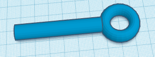
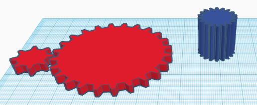
Remember this part?
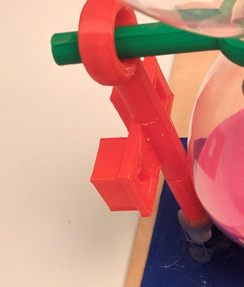
What if I were to move it up, nearer the horizontal bar so that my small gear could directly meet the larger gear?
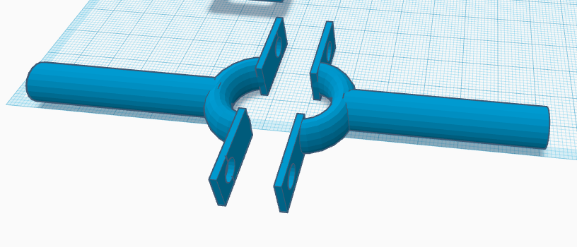
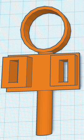
So I quickly designed this:
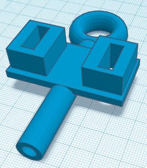
The blocks are for mounting the motor. Note, the distance between the blocks must be larger than the small gear diameter, otherwise it won't have space to turn.
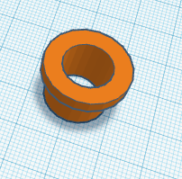
Until my bearings arrive, I also created this - a diameter-reducer to hold the horizontal bar more steady.
The following photos illustrate how the pieces fit together. Note the small cog turns in the space between the blocks.
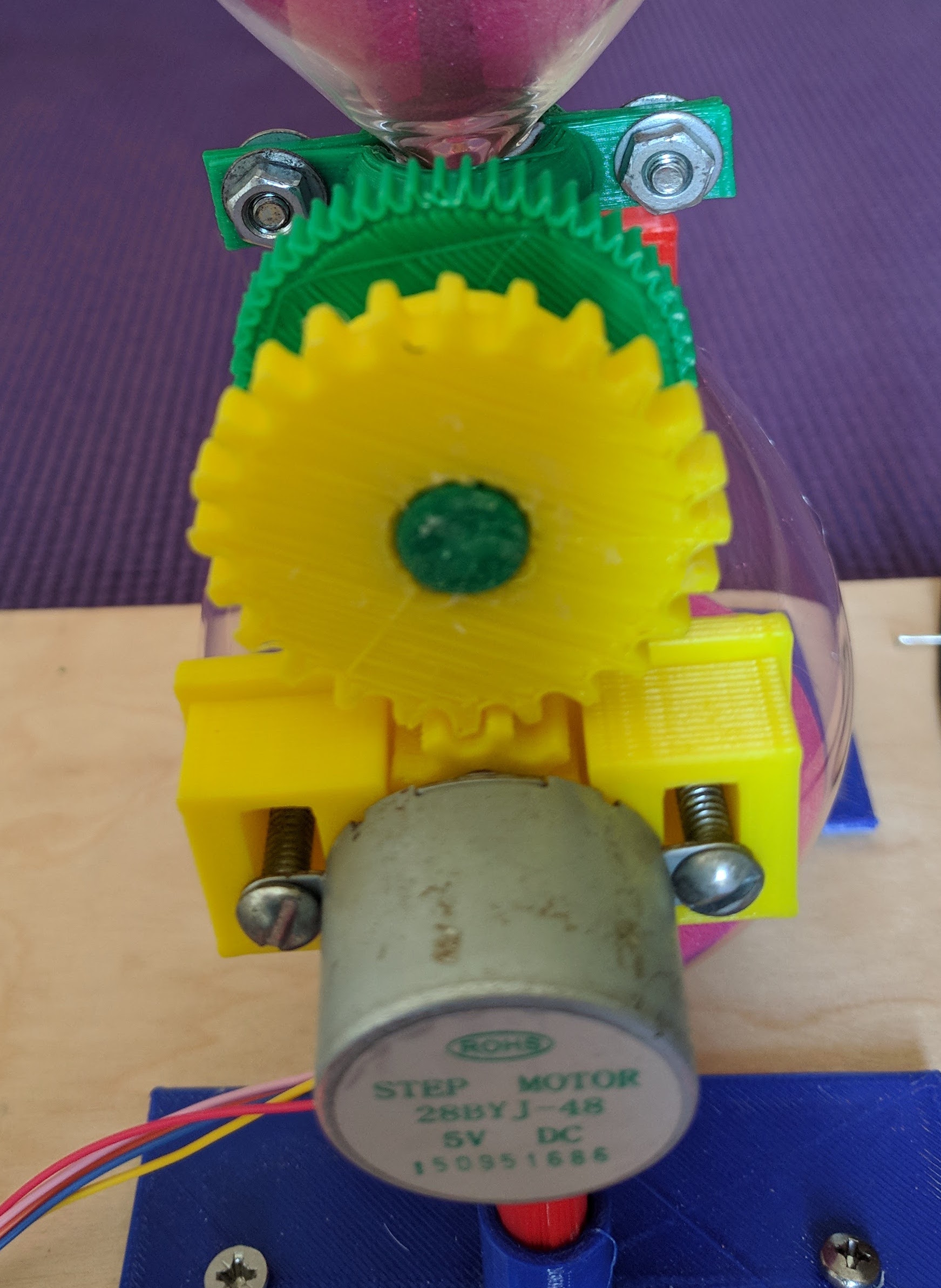
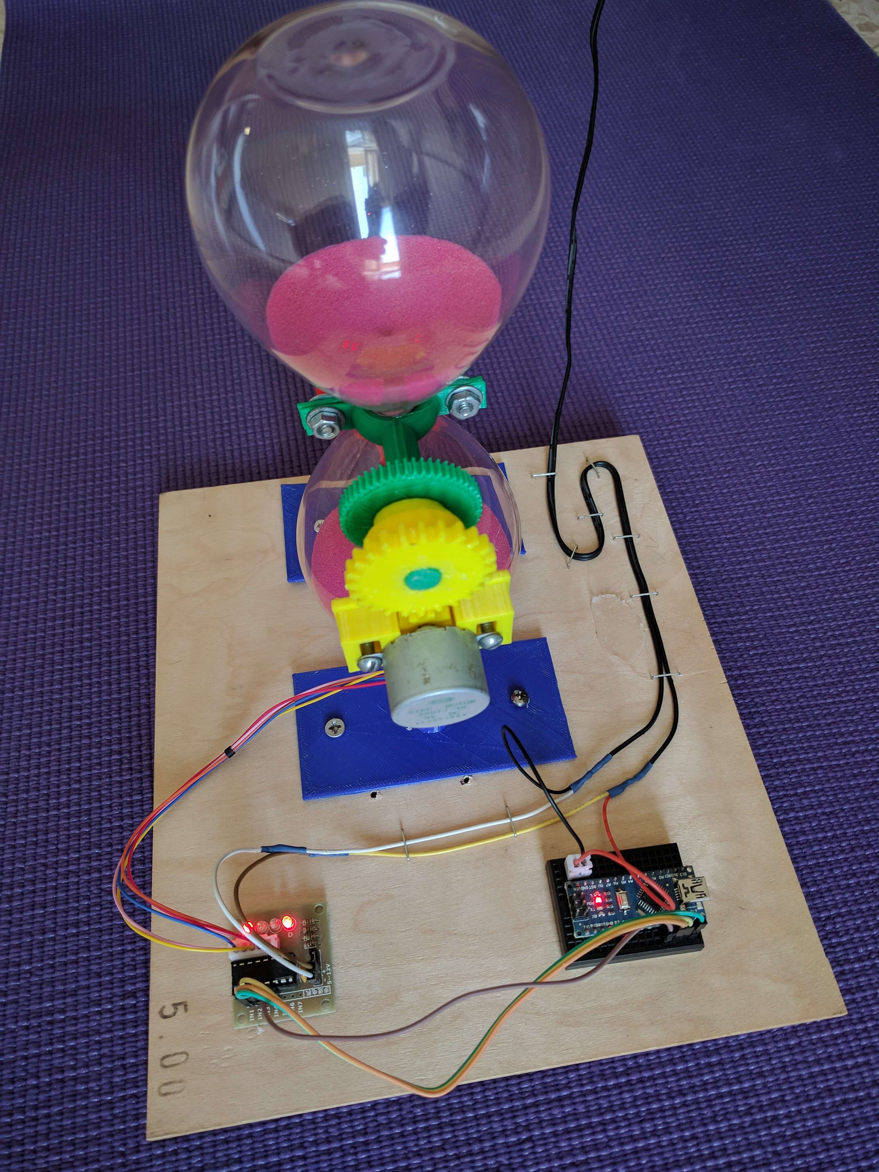
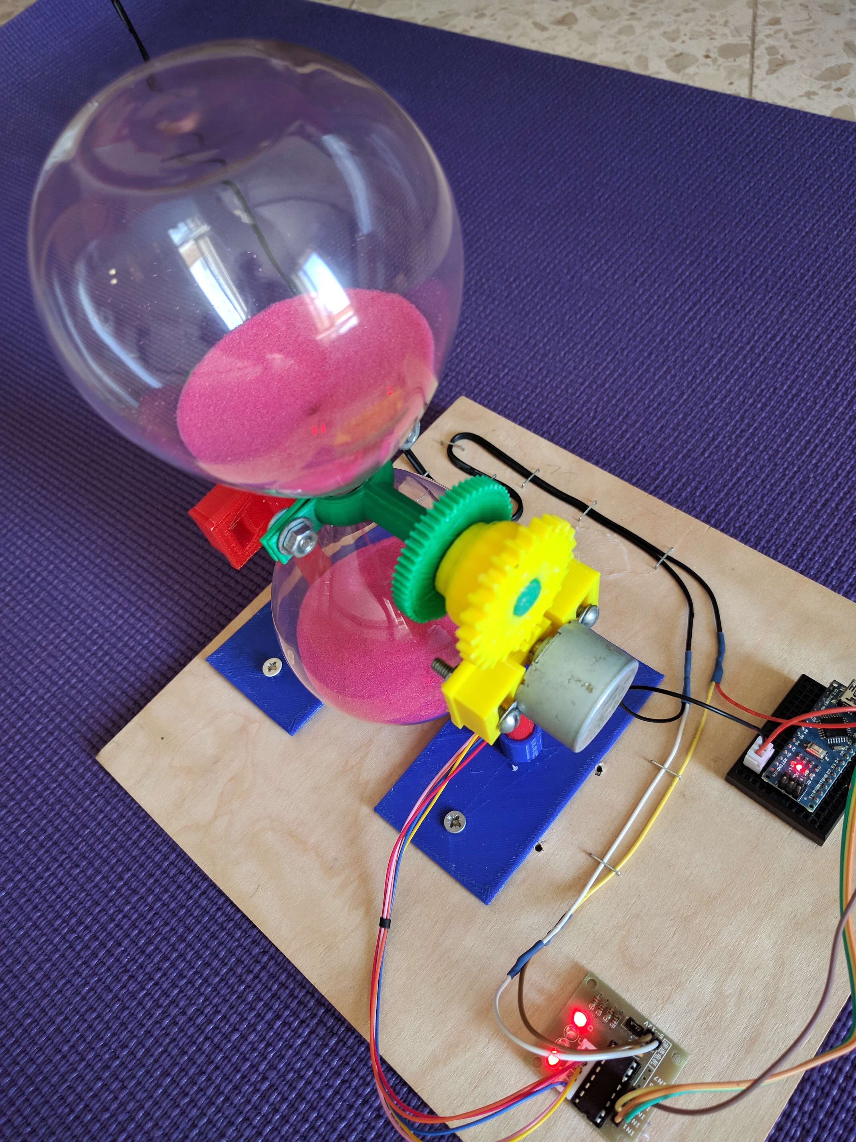
The rest of the project, as you can see, is a cheap Chinese Arduino Nano, and the BYJ48 stepper controller. The Arduino sketch is very simple; it just turns the motor every 30 minutes. The motor is attached to pins 8,9,10,11 of the Arduino:
#include <Servo.h>
#include <Stepper.h>

  const int stepsPerMotorRevolution = 32;  //No of steps per internal revolution of motor,
  const int stepsPerOutputRevolution = 32*64; //no of steps per revolution of the output shaft
  const int motorpin1 = 8;                    //Assign motor  pins to Arduino pins
  const int motorpin2 = 9;
  const int motorpin3 = 10;
  const int motorpin4 = 11;

  // initialize the stepper library on pins 8 through 11, Motor rev steps, initialise firing sequence 1-3-2-4

Stepper myStepper(stepsPerMotorRevolution, motorpin1,motorpin3,motorpin2,motorpin4);

  void setup() {
    myStepper.setSpeed(800);
  }

  void loop(){
    myStepper.step(3072);
    delay(1800000); //adjust for required delay between rotations

  }
Before you watch the YouTube video, remember, the real Inverter stops for 30 minutes to allow the sand to flow through. In the video, it only stops for half a second for illustration purposes.
You can download my stl files for 3d printing here. Tinkercad apparently sets a time limit on sharing, so if the link is dead, comment below and I'll refresh it.
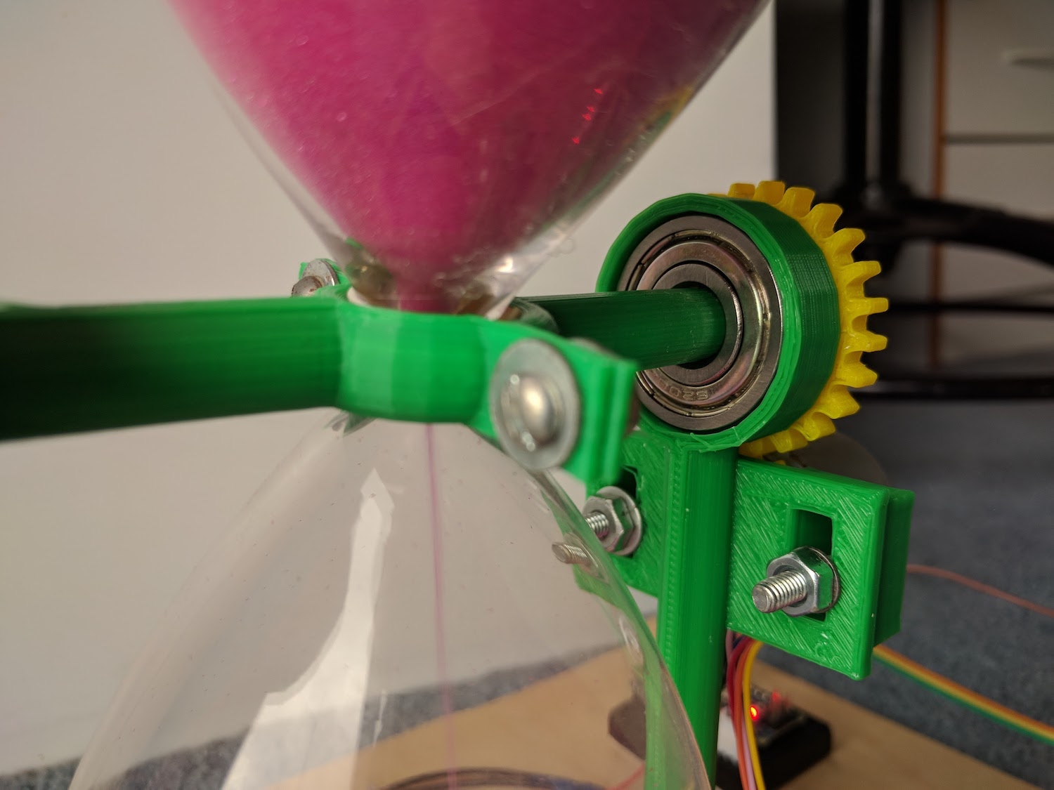
Update - Oct 2017
My bearings arrived from China and I had fun re-designing the vertical supports to incorporate them. The entire model is working much more smoothly now.
Here's what the new column looks like in Tinkercad.
Here it is in place:
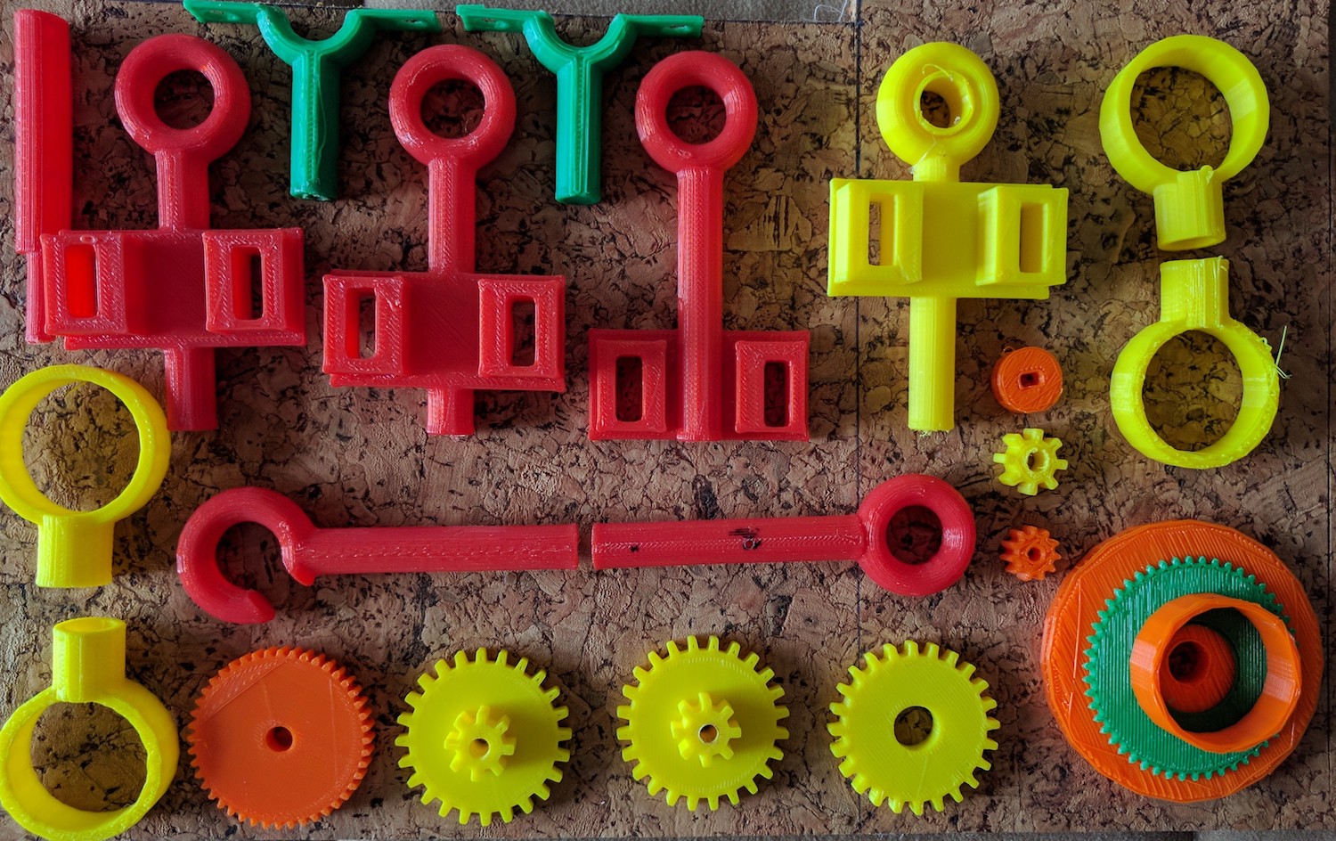
Here are the discarded parts I printed trying to get things right.
And here's the video of the inversion with bearings in place.