As I've mentioned so many times in my blog posts, I've never studied electronics or engineering. Consequently, I come at my projects entirely as an amateur - which means that when I finally figure out how to do something, I'm able to guide others like myself through the technical complexities, explaining step-by-step how to get things working.
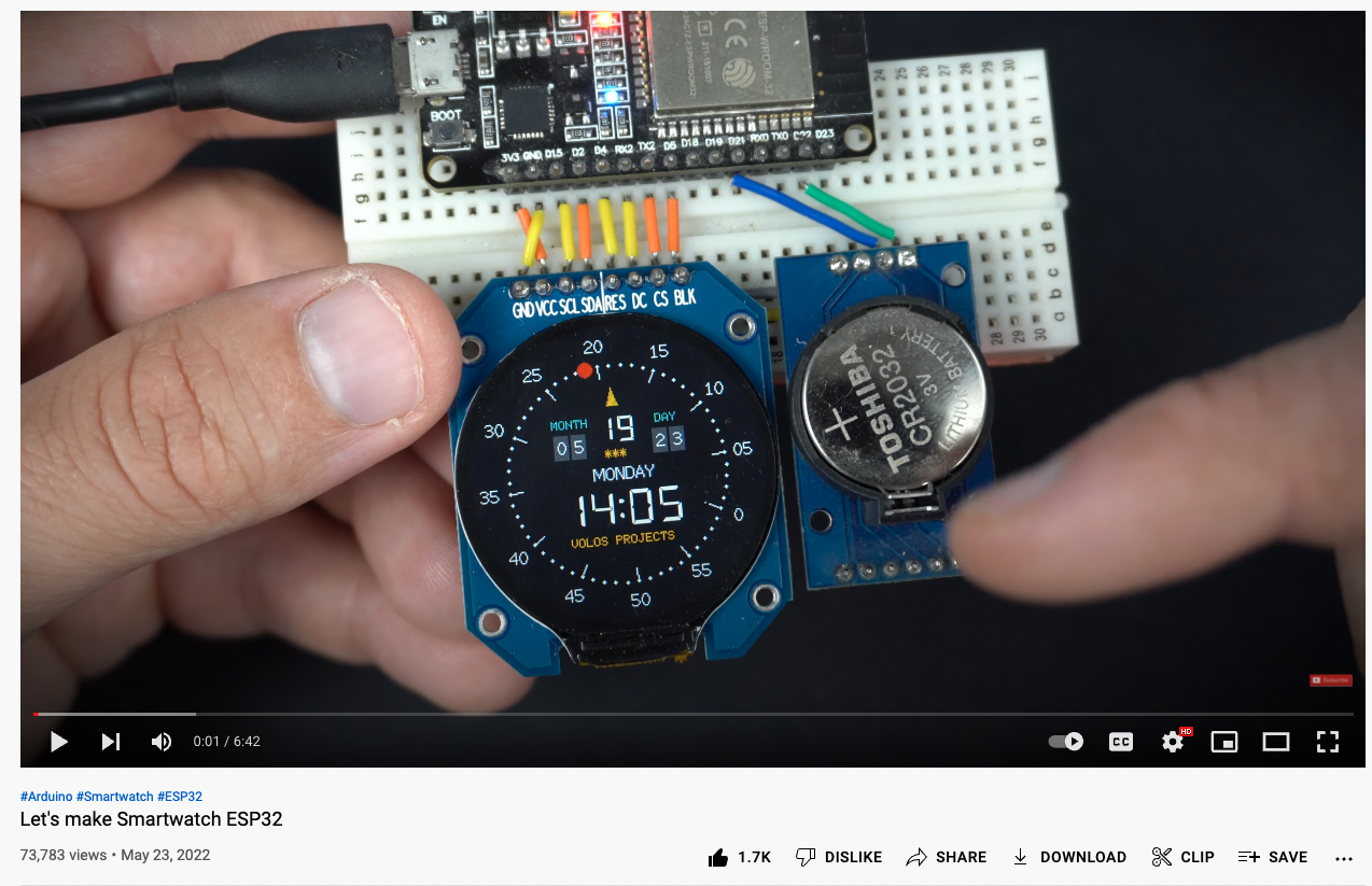
For about a year I've been a keen follower of Volos Projects on Youtube. His work is outstanding and he makes really attractive gadgets. More than once I've found myself ordering parts simply so that I could build one of his projects.
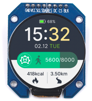
This happened last month when I came across his GC9A01 240x240 display video. It just looked so good, I immediately ordered one from Aliexpress.
When I was ordering it, I was aware that I didn't have an ESP32, but I assumed that my trusty old ESP8266 Dev Boards would suffice.
Lesson One: Beware of my first mistake
The screen arrived in a surprisingly short time, and I set about scouring Google for instructions.
First, I thought I'd get the screen up and running with an Arduino Uno - just to see that it works. I connected everything up, and only after I'd failed repeatedly did I realize that my version of the GC9A01 is not 5v tolerant. Of course, in my amateur stupidity, I believed that connecting the VCC pin on the screen to 3.3v on the Arduino was sufficient. It was only afterwards that I realized that the Arduino Digital Pins are 5v - and I could have ruined the screen before I even got started.
ESP8266
Worried now that I'd damaged the GC9A01, I was desperate to see any image at all. As I knew that the ESP8266 is 3.3v, I searched for a script to get it working. I tried various libraries and Youtube videos, but still I couldn't get an image. I was convinced I'd destroyed it with over-voltage.
Raspberry Pi Pico
In a last-ditch effort, I pulled out a Raspberry Pi Pico and after some searching, I found concise instructions on the PCBWay website. After connecting all my wires, I finally got the GC9A01 working with the excellent Arduino TFT-eSPI library. At this stage, all I could do was view the library's examples (of which there are many), but at least I confirmed that the screen hadn't been damaged.
ESP32
But I was still determined to make Volos's watch, and the only way I could do that would be to acquire an ESP32.
So I waited for China Post to bring it. I ordered a cheapie, assuming they're all basically the same. It arrived about two weeks later.
In preparation, I plugged the ESP32 into my Mac and fired up Arduino, intent on flashing blink.
Of course, the serial port was nowhere to be seen. Nothing. I tried various permutations of pushing the ESP's buttons, both while it was powered and during power-up. Nothing at all. Dead as a doorpost.
So then I Googled it.
Serial Chip
Turns out the cheap versions of the latest ESP32's come with a different serial programming chip. So, first I looked at the specs on the Alixexpress page. It authoritatively informed me that the chip is a CH9102X. So, off I went in search of a the Mac driver for the CH9102X. A quick search revealed this post. Now, if you look carefully, you'll notice something that I didn't - which gave me another hour of confusion and frustration.
While the question asked in stackexchange refers to the CH9102X, the link that's given is for a driver for the CH34XSER chip. I didn't notice, and simply downloaded the CH34XSER driver. I then went through the extremely nerve-wracking procedure of installing it into my Mac while ignoring progressively-hysterical security warnings as I went along.
As instructed, I restarted my Mac, entered Arduino, and plugged in my ESP32.
It was there! I could see it!
I loaded up the blink example, changed my board to ESP32, and hit upload. It compiled the code and went into upload, and .... ERROR!
I tried again....
ERROR!
I couldn't figure it out and being the amateur that I am, assumed it was still a driver problem. I tried all sorts of things and nothing worked.
Fortunately, with the driver, comes a small instruction manual. Even more fortunately - unlike the site itself - the manual is in English. It contains a wee bit of troubleshooting so I diligently followed the instructions.
To see if my driver was installed properly, within Mac Terminal:
cd /dev
ls tty.wch*
If the result is something like tty.wchusbserial21311 the driver is properly installed.
I did this, and yes, my driver was properly installed.
I tried again - but still it Errored on the upload. At this stage, I still hadn't noticed that the driver I'd installed wasn't the driver mentioned on the Aliexpress specs page.
After some more fiddling, I suddenly noticed - I'd installed the wrong driver. I went looking for the CH9102X driver - but I kept coming back to the CH34XSER page.
Aha, I thought, why not look at the chip itself!
I took a closeup with my phone and expanded the photo on my screen. The chip was clearly a CH340G!
Lesson Two - don't rely on Aliexpress specs
So, in the end, I HAD installed the correct driver - and the specs on Aliexpress were wrong. Hence, my second Public Service Announcement: if Ali's specs say it's a CH9102X chip, check to see if it is, in fact, a CH3400.
So why wouldn't the damned thing upload?
I spent another couple of hours trying it on another computer, pressing buttons, searching Google, and scratching my head. I even tried another cable.
It's the cable again, Idiot!
I learned a long time ago that we should always use the shortest cable possible. Most of mine are 15cm.
So, I tried another cable - but it still didn't work. I was about to give up for the night when I had a brainstorm.
I looked down at my Mac. For convenience purposes, I have a USB extension cable permanently attached. It's so much easier to plug and unplug that way, rather than reaching to the back of my Mac Mini. Aware that long USB cables sap power, I connected my 15cm cable to the ESP32 and plugged it directly into the Mac.
Blink uploaded in a blink and my little LED starting flashing!
This had never happened before with an ESP8266 or a RasPi Pico. There wasn't enough power getting to the ESP32 to flash it.
Getting to Volos
Now that I was successfully flashing my ESP, it was time to get back to the Volos watch. I opened up VolosProject's video and went looking for the wiring diagram. First I searched at his GitHub page but it only contained the code. So then I just looked at his amazing video. It was pretty clear where each wire should go, so I wired mine the same.
With my new-found skills of ESP32 flashing, I downloaded his excellent code, stuck it in the Arduino IDE, and hit UPLOAD. The sketch flashed in an instant.
Nothing. Blank screen. Not a cheep.
Yet another wild goose chase
So now I thought it was my wiring. My first assumption was that my ESP wasn't configured the same as the one in the video. I looked closely and noticed that his RX2 and TX2 pins are labeled D16 and D17 on my board. Everything else looked fine, but this particular observation sent me on a pointless quest for the pinout of my precise ESP32 board. I must have looked at hundreds of them, but I couldn't find my exact board. Fortunately, more than one photo indicated that D16 and D17 can be RX2 and TX2 - so I was making progress, but still nothing would work.
By this time, I was just jumping around from point to point on his video, looking for something I'd missed. On one such jump, at minute 4:12, he mentions his previous video that explains how to set up the display.
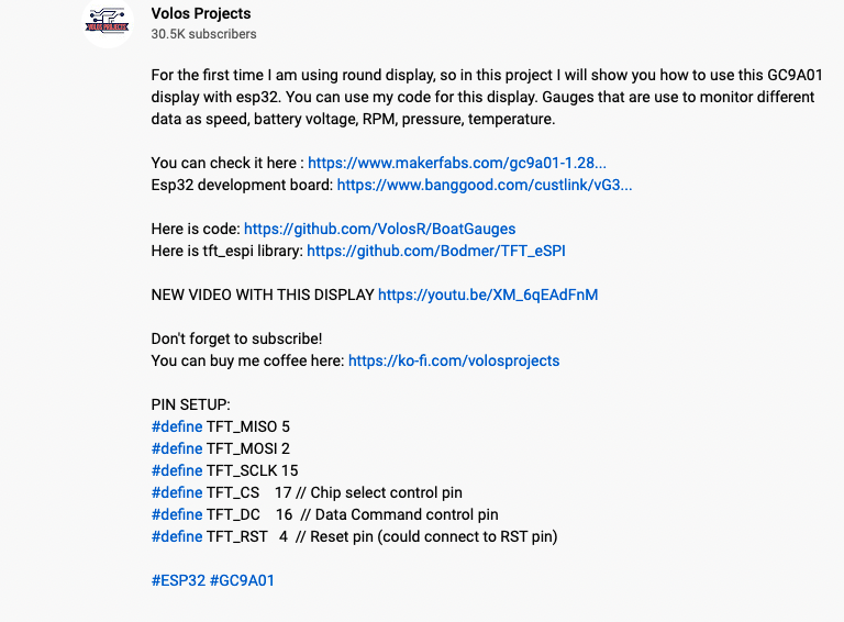
So back I go to his previous video and there at the bottom of his description is the pin setup!
It's so hard when you've never been trained...
So there I had it, the MISO pin, the MOSI pin, the SCLK pin - everything you could want. Except that my screen was labeled:

So which pin was MOSI? Which was MISO, and SCLK - is that the same as SCL?
More Googling. More searching. What's the difference between MISO and MOSI and how do they relate to SCL and SDA? Around in circles I went, getting more and more confused.
Come on, Dear Reader, you've got to admire my perseverance. I've been at this for hours and I refuse to give up.
Nearly there
I must have spent about two hours on MISO and MOSI, SPI and I2C and about every other electronics acronym in the book. I was still searching for my wiring problem, and getting nowhere at all.
What's the equivalent of RTFM for video? WTFV?
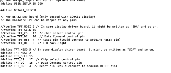
In the end, I did what I should have done at the outset: watch the F..ing video! In it, Mr. Volos tells his viewers specifically what to do. This includes, among other things, going into the TFT.eSPI library and adjusting the Setup200_GC9A01.h file.
Obedient as I am, I opened the file and saw this pinout defined:
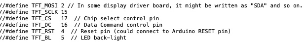
Always looking to do it the hard way, I then tried to figure out with pins to change. Which of them is MISO? - it's not mentioned there at all. It does say, "In some display driver board, (sic) it might be written as "SDA" and so on." - but to the amateur this doesn't help me very much.
In the end, and in despair, I just decided to comment out all existing pins, and simply copy the new ones exactly as Mr. Volos had written them. I was skeptical because I couldn't see how the LED back-light could be the MISO pin.
I watched through to the end of the video then powered up the ESP32.
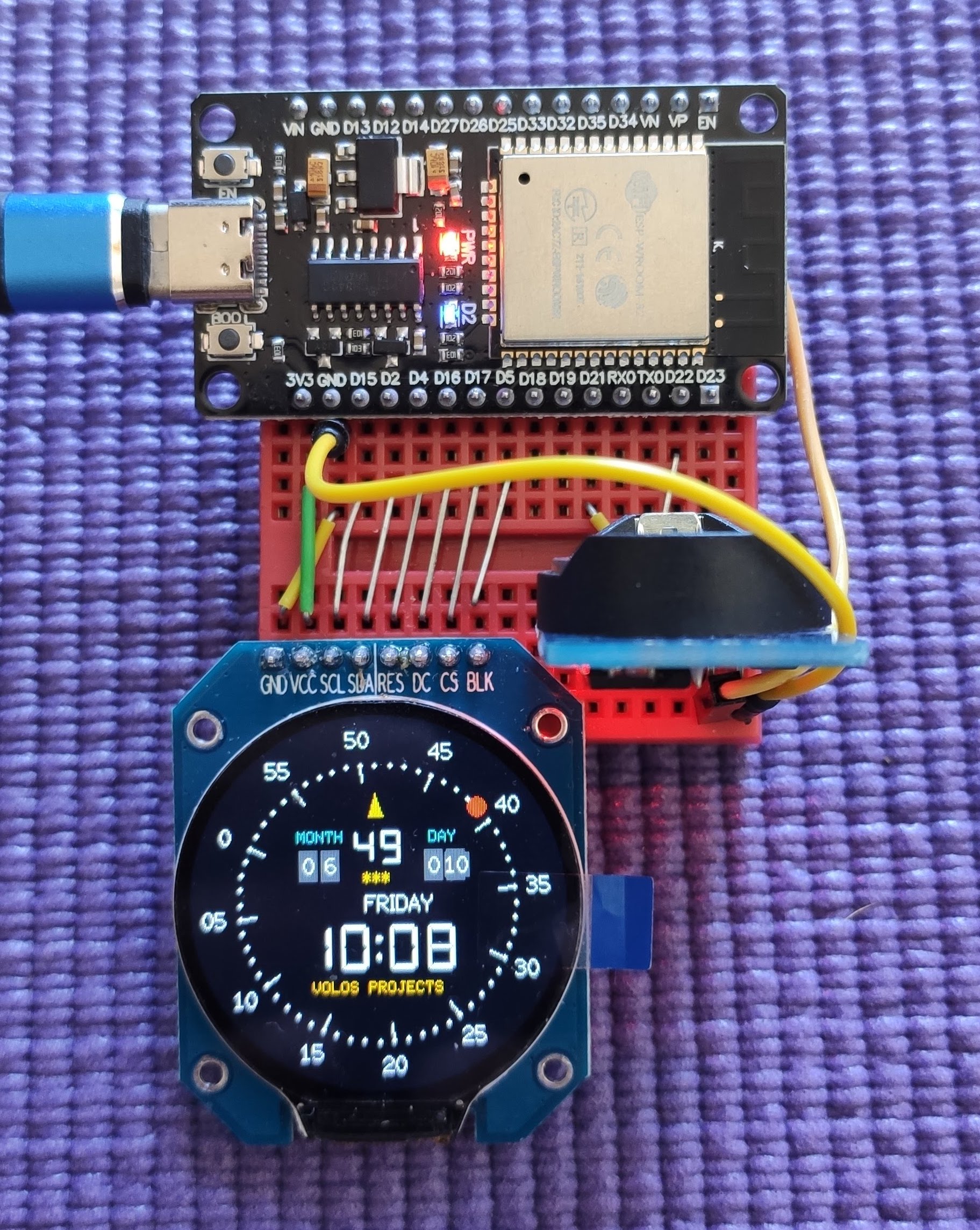
I couldn't believe my eyes. After several hours of struggling, a very unstable Volos Watch appeared on the screen. It has lines all over it, but at least I was one step closer.
Power, I thought. The RTC - which requires 5v - is draining power from the screen. I turned it all off and looked for the VIN pin on the ESP. I then attached it to the RTC's VCC. I powered up again, and finally I had a perfect picture!
Setting the time
Of course, that wasn't the end of it. The time showed 3:49 and it was 11pm. It was also about seven months ahead of me and it certainly wasn't Wednesday!
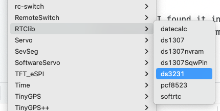
My Volos Watch was showing the time it got from the RTC, so I needed to set the latter's time. I'd had experience before of the DS3231 Real Time Clock (RTC). In the past I'd found some obscure library to do this, but as usual, it wasn't simple; it required manually setting the time and date, and predicting what time it would be when the sketch had finished uploading! I knew there must be an easier way.
Fortunately, I found it in Adafruit's RTC Library. All I needed to do was load up the DS3231 example and the library read my system time, then set it precisely on the RTC.
Staples are your friend
I love the way Volos presents his projects. It's always so neat, compact and tidy. I wanted to emulate this as best I could, so I utilized one of my favourite wiring techniques. As you'll see from the photo, by using regular staples, you can cut down wiring considerably and it makes for a very neat package.
Who is going to create a 3d printable case?
Now I have a beautiful, compact watch attached to a mini breadboard, but obviously it needs a case. I tried to make something in Tinkercad but like everything else I design, it was just circles and squares and looked like a 7 year-old's creation. Anyone ready to design something wonderful?