The need for multiple switch settings, aka jumper settings, to set an ID/ program options has been crucial to my recent projects. As I build IoT devices that require self-identification, I have to create an ID number on each device.
In hardware, the least expensive way to accomplish this is to use a 2xn female header with shunt-jumpers to set different values. A well known example of this approach is the IDE disk drive, with its five jumpers.
I was looking for a more elegant solution to set an ID number.
Option one, pictured below on the left, which I explored but ultimately didn’t use because of the cost factor, is a rotary switch. This rotary switch is the Nidec Copal PN SH-7070TB, available from Digi-Key for $2.16 each.
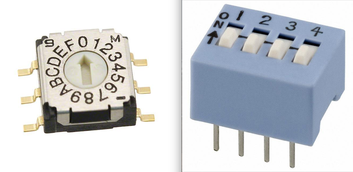
Instead, I opted to use a DIP switch, pictured above on the right. This is the CTS Electro-Components 206-4, available from Digi-Key for $0.79 each.
How do we hook up the DIP switch to the Arduino? The most straightforward way is:
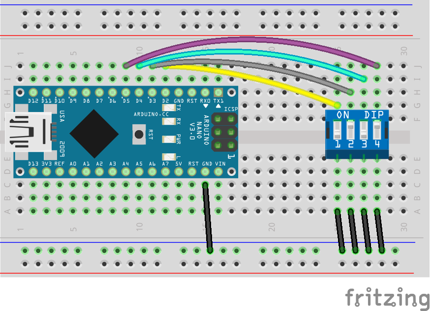
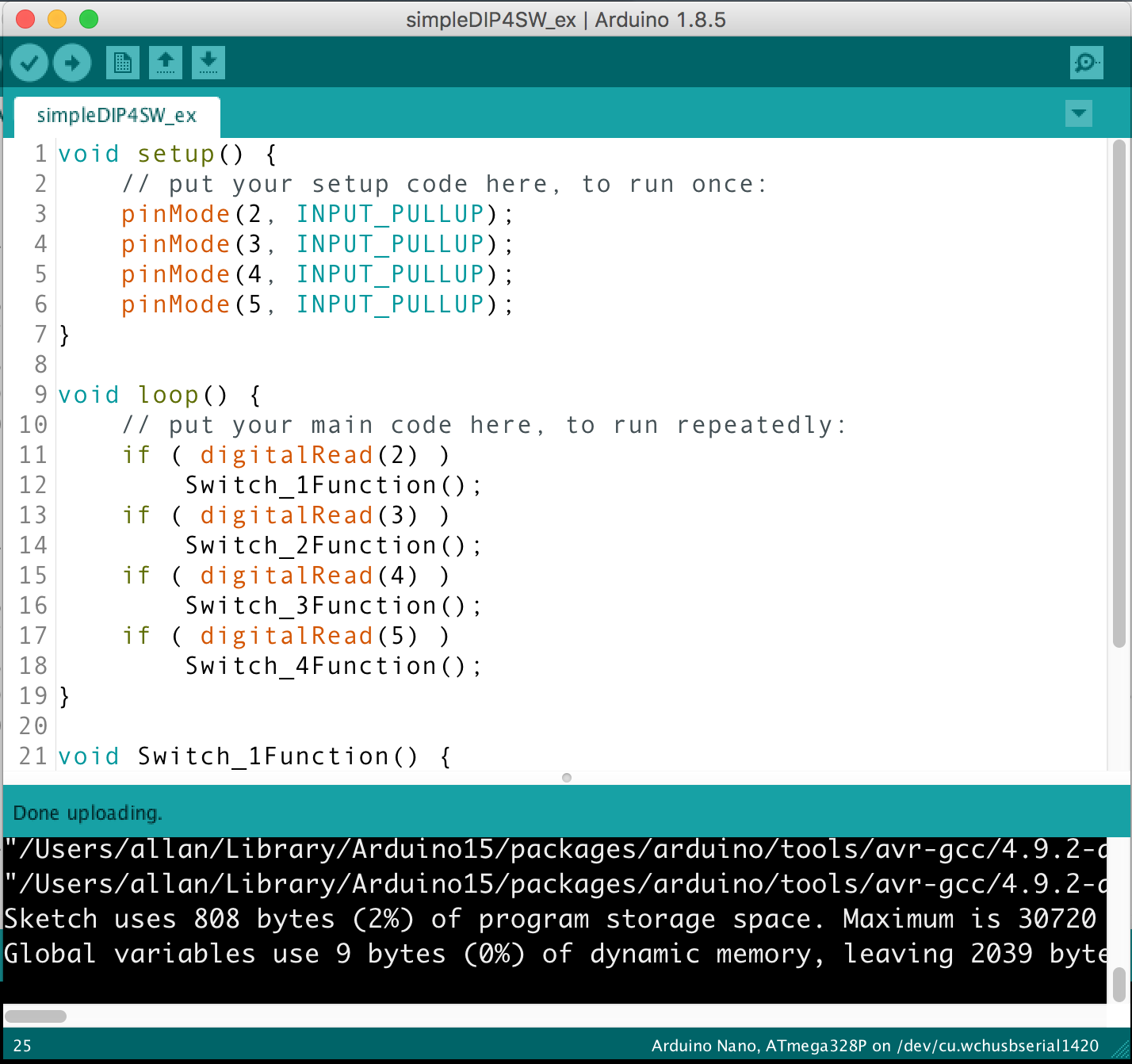
Each switch position is wired to a separate Arduino digital pin. The “off” side of the switch leg is grounded. For example, each pin can be programmed as follows:
However, if your application needs most of the digital pins, or your processor has very few digital pins -- for example, on a ATtiny85 shown below -- then you need to implement a different solution.
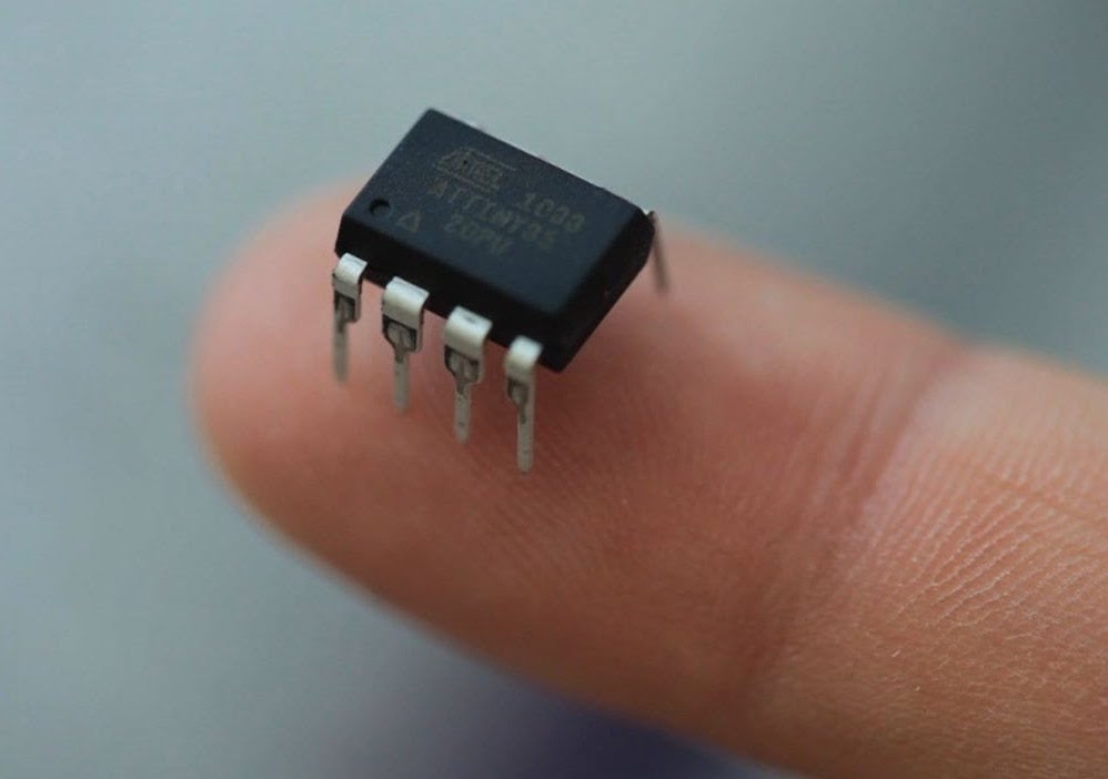
The above photo is an ATtiny85 processor, which provides an Arduino environment, but limited to only 5 pins; 3 of those pins may be used for analog inputs.
Here is a solution that utilizes one Arduino pin, and eight resistors, an R-2R resistor ladder network.
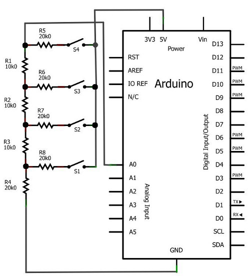
The above circuit is called an R–2R resistor ladder network
See https://en.wikipedia.org/wiki/Resistor_ladder
The advantage of this ladder network is that each switch leg contributes an exponentially stepped value to the measured voltage. In the circuit shown above, the voltage is measured at A0. Only two resistor values are used, shown here as 10K and 20K , but in general, R and 2R.
However, wanting to simplify this even further, I devised a resistor network that uses one Arduino pin and 5 resistors. Again, this solution produces only an analog voltage, proportional to the switch value.
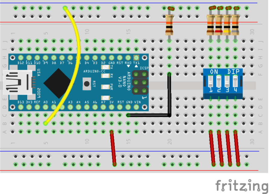
Here is my Circuit Diagram, breadboard view:
Here is my Circuit Diagram, schematic view:
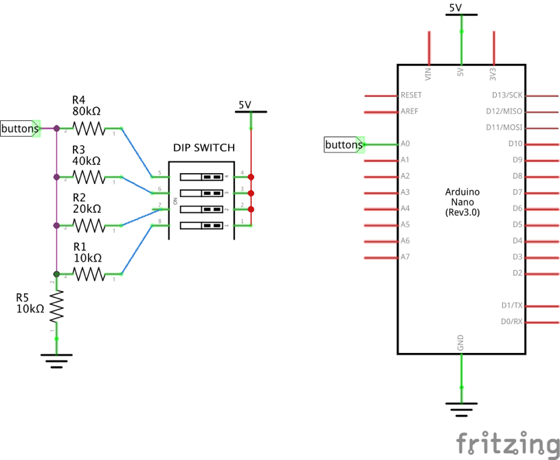
This circuit will allow a single Arduino analog input pin to read all of the switch values, which are then decoded in software.
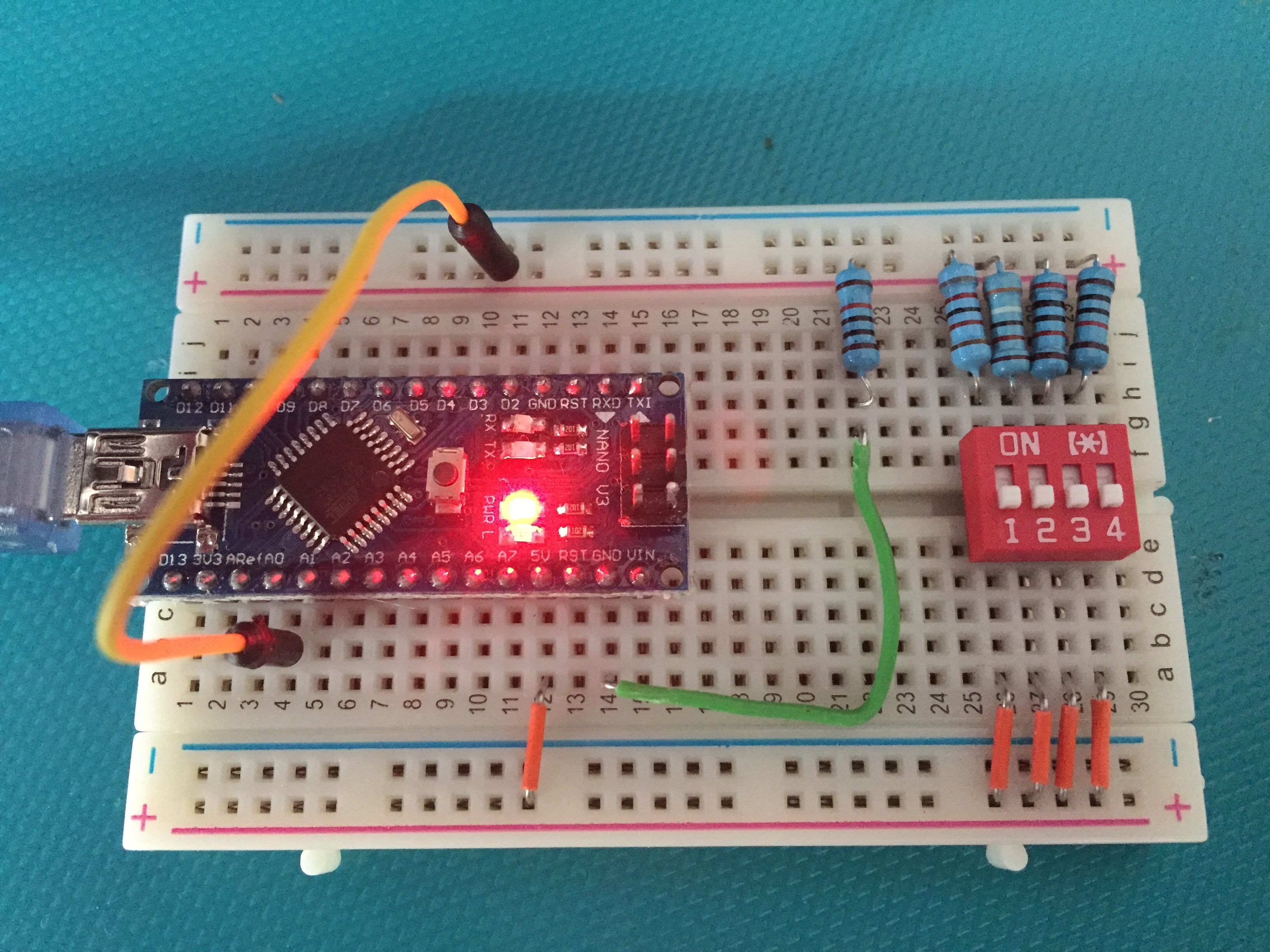
Voila! Let’s build it and test it. Here is my constructed breadboard:
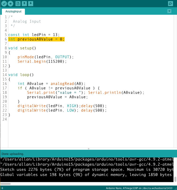
Next, we need some testing software. Here is a little Arduino sketch that I adapted from the Analog Input example sketch.
We run the code, try all 16 switch settings, and record the results in a table.
| Switch 1 2 3 4 |
ID number | analogRead |
|---|---|---|
| 0 0 0 0 | 0 | 0 |
| 0 0 0 1 | 1 | 108 |
| 0 0 1 0 | 2 | 208 |
| 0 0 1 1 | 3 | 280 |
| 0 1 0 0 | 4 | 341 |
| 0 1 0 1 | 5 | 392 |
| 0 1 1 0 | 6 | 441 |
| 0 1 1 1 | 7 | 479 |
| 1 0 0 0 | 8 | 512 |
| 1 0 0 1 | 9 | 542 |
| 1 0 1 0 | 10 | 571 |
| 1 0 1 1 | 11 | 594 |
| 1 1 0 0 | 12 | 615 |
| 1 1 0 1 | 13 | 634 |
| 1 1 1 0 | 14 | 653 |
| 1 1 1 1 | 15 | 669 |
This is a very good result because the analog values shown in the highlighted column are monotonically increasing, with plenty of space between each successive value.
We can now write a function that reads the analog value of the resistor network and returns an ID number in the range of 0..15.
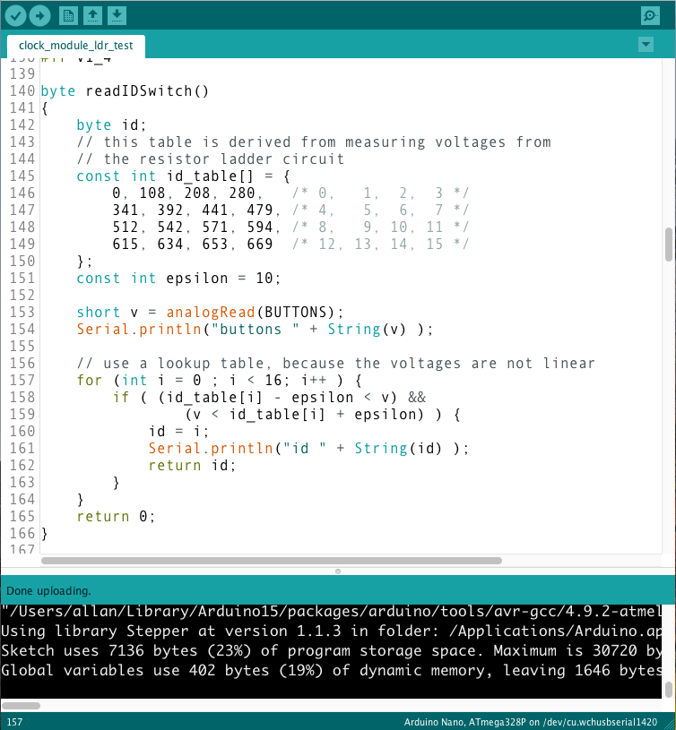
This function is simply called from setup() and returns the ID number which is then stored in some global variable.
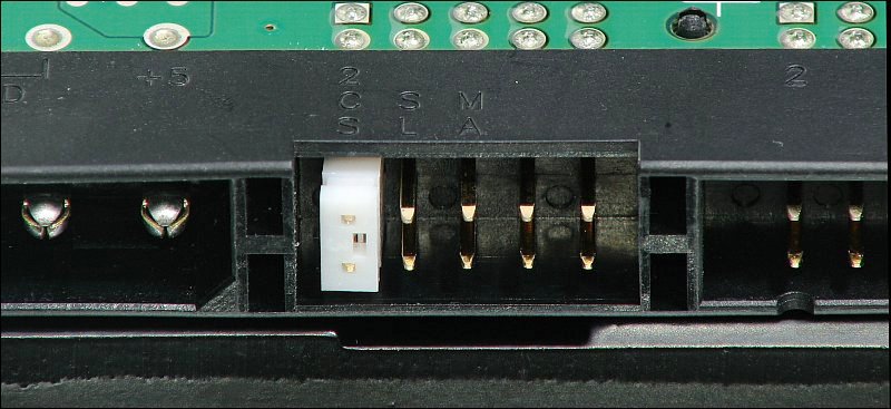
I’ve used this circuit on several boards that I have designed. Here is a close-up photo of one of my boards, where we can see the resistor network of five surface mount resistors next to the DIP switch.
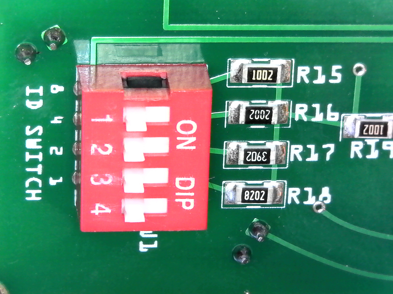
As an aside, this photo was taken with a very inexpensive ($20) USB-attached microscope. This inspection microscope is now an invaluable tool on my workbench. We can even read the resistor values on the SMD parts:
R15, 1002 = 10K Ohm
R16, 2002 = 20K Ohm
R17, 3902 = 39K Ohm
R18, 8202 = 82K Ohm
This small circuit, plus that little bit of Arduino code, has been reused successfully now on three circuit boards. An inexpensive yet powerful solution to your ID problem!
The little snippets of Arduino code, and circuit sketches in this blog may be
viewed or downloaded on my github repository.