The purpose of this project is to build a countdown timer comprised of two 7-segment displays. Several interesting challenges are solved or resolved:
- How to interface a 7-segment display to the Arduino directly – without using a MAX7219 chip.
- How to write concise and efficient Arduino C code to drive the 7-segment display, and represent the digit displays in a data structure. This is achieved in just three lines of code!
- Understanding the concepts of the Arduino
setup()andloop()functions. And the use of time (milliseconds and seconds) in a program.
In future blog entry I’ll illustrate how to reimplement this project using a higher level of integration, to both reduce the code and reduce the circuitry.
Why?
As a former manager for an embedded computing development group, this was an exercise for creating a low-level interface. There are 3 challenging elements in this exercise:
- how to hook up a common-anode 7-segment display
- how to write extremely low-level code without resorting to a library
- how to display a digit efficiently, with proper use of a data structure.
Parts
I used an Arduino Uno, the most well-documented microcontroller available. This is in contrast to several recent blog posts using Raspberry Pi’s or the ESP8266 microcontroller. But here, let's get back to basics.
You’ll Need:
- An Arduino Uno and USB cable
- a Breadboard plus jumper cables
- a 2-digit 7-segment display unit
- a handfull of 330 ohm resistors
Let's Start
Common Anode vs. Common Cathode
In connecting LEDs to your Arduino, there are two ways to wire the circuit.
This is the typical circuit:
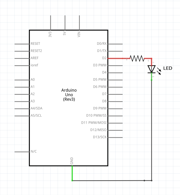 The plus side (or anode) is wired to the Arduino's digital pin (through a current-limiting resistor), and the minus side (or cathode) is wired to ground. You apply HIGH to the pin to light the LED.
However, the other direction works as well.
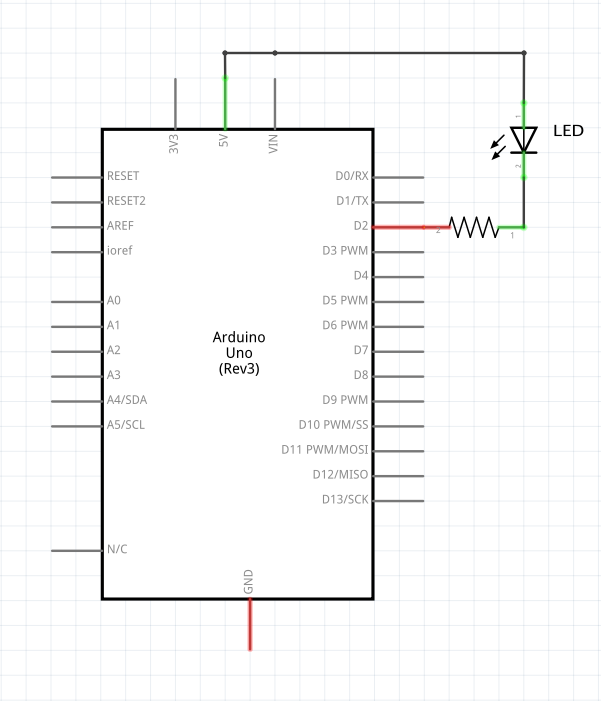 In this case, the cathode (-) is wired to the Arduino's digital pin (through a current-limiting resistor), and the anode (+) is wired to +5. You apply LOW to the pin to light the LED.
7-Segments of LEDs
We will be using a 2-digit 7-segment LED for this exercise. Our common anode 7-segment display is similar to the 7 LEDs, with all the anodes tied together.
When 5v is applied to the common anode and the cathode or negative side of the LED segment is pulled to ground (through a 330 ohm resistor), current flows and the segment is lit. If the cathode is held to 5v, no current flows and the segment is unlit.
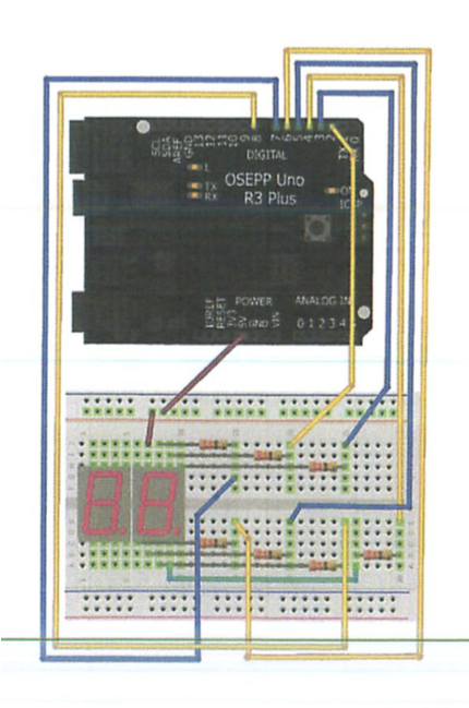
Wiring the circuit
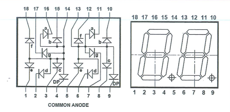
Using the diagram above we can see how to wire the circuit to interface the digits, as illustrated in the wiring schematic below. This shows only the right-most digit wired.
Segment signal names
The segment names a, b, c, d, e, f, g are completely standardized on every 7-segment display.
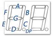
We will use the most straightforward solution of wiring each segment to a different Arduino digital pin, according to this list documented in the comments:
/**
 *
 * @notes       The following Arduino Pins are attached:
 *
 *              name    Arduino   7 Segment display
 *              -----   ----      -----
 *              D1-a    D2        11
 *              D1-b    D3        10
 *              D1-c    D4        8
 *              D1-d    D5        6
 *              D1-e    D6        5
 *              D1-f    D7        12
 *              D1-g    D8        7
 *              anode   +5        13
 *
 *              D10-a   D10       16
 *              D10-b   D11       15
 *              D10-c   D12       3
 *              D10-d   D13       2
 *              D10-e   D14/A0    1
 *              D10-f   D15/A1    18
 *              D10-g   D16/A2    17
 *              anode   +5        14
 */
Programming
Using the finished circuit, we can display digits 0 through 9 on both the left and right digits.
In this exercise, we will be writing an Arduino sketch that displays a countdown timer counting down for 1 minute, from 60 down to 0. At zero, the display should flash to indicate that the countdown is complete.
Creating digits in just three lines of code
Most of the sketches available to run a 7-segment display have code for each digit. So, if you need the number “6” the code will light each segment making up the number. This requires a separate function for each digit – which uses up precious Arduino code space.
// sample code to draw a 6 on the 7-segment display
void six()
{
    digitalWrite(a, HIGH);
    digitalWrite(b, LOW);
    digitalWrite(c, HIGH);
    digitalWrite(d, HIGH);
    digitalWrite(e, HIGH);
    digitalWrite(f, HIGH);
    digitalWrite(g, HIGH);
}
As you can see, creating a function for each digit is a tedious process. We can improve on this. Here is how to create, in three lines of code, all 10 digits. Moreover, this can easily be adapted to extend to a full character set.
First, we made a table of the ten 7-segment symbols, and the state of the signals a, b, c, d, e, f and g for each symbol.
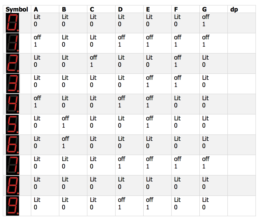
Now that we can see this table, it becomes clear how to solve the problem with a simple data structure rather than a lot of code. Translating the table above into C code is straightforward:
const byte numbers[10][7] = {
                             // 0: segment lit, 1: unlit
  // a  b  c  d  e  f  g
    {0, 0, 0, 0, 0, 0, 1},   // 0
    {1, 0, 0, 1, 1, 1, 1},   // 1
    {0, 0, 1, 0, 0, 1, 0},   // 2
    {0, 0, 0, 0, 1, 1, 0},   // 3
    {1, 0, 0, 1, 1, 0, 0},   // 4
    {0, 1, 0, 0, 1, 0, 0},   // 5
    {0, 1, 0, 0, 0, 0, 0},   // 6
    {0, 0, 0, 1, 1, 1, 1},   // 7
    {0, 0, 0, 0, 0, 0, 0},   // 8
    {0, 0, 0, 1, 1, 0, 0},   // 9
};
Using the data structure numbers, we write a function that can display any digit (or symbol) we desire. That is followed by a function which displays any two-digit number from 0 to 99.
// display the digit {0..9} in either the ones or tens DIGIT
void sevenSegmentDigit(byte digit, byte pin) {
    for ( byte i = 0; i < 7; i++, pin++ )
        digitalWrite(pin, numbers[digit][i]);
}

// the  1's digit pin a-g are digital pins 2-8
const byte ONES_DIGIT = 2;
// the 10's digit pin a-g are digital pins 10-17
const byte TENS_DIGIT = 10;


// display the two-digit number {00..99} in the
//    two 7-segment displays
void sevenSegment_nn(int nn) {
    sevenSegmentDigit((nn / 10) % 10, TENS_DIGIT);
    sevenSegmentDigit(nn % 10, ONES_DIGIT);
}
Finished Device
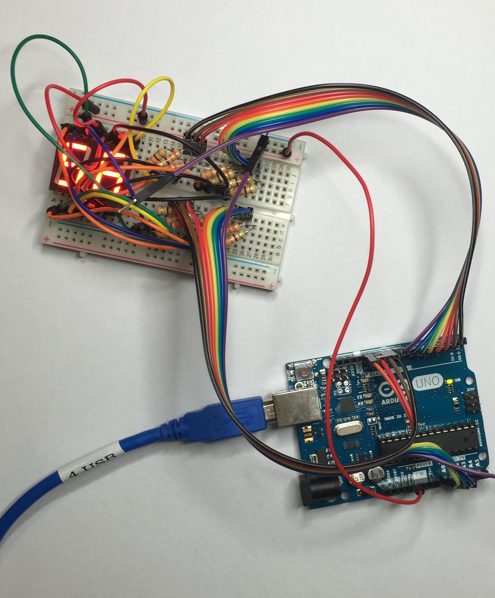
device in action...
Finished code
/**
 * @file        countdown_7segment.c
 *
 * @brief       exercise to create a countdown timer
 *              using a 2-digit 7-Segment display
 *
 * @history     exercise proposed Oct 28th, 2015
 *
 * @author      Allan M Schwartz, allans@CodeValue.net
 *
 * @notes       The following Arduino Pins are attached:
 *
 *              name    Arduino   7 Segment display
 *              -----   ----      -----
 *              D1-a    D2        11
 *              D1-b    D3        10
 *              D1-c    D4        8
 *              D1-d    D5        6
 *              D1-e    D6        5
 *              D1-f    D7        12
 *              D1-g    D8        7
 *              anode   +5        13
 *
 *              D10-a   D10       16
 *              D10-b   D11       15
 *              D10-c   D12       3
 *              D10-d   D13       2
 *              D10-e   D14/A0    1
 *              D10-f   D15/A1    18
 *              D10-g   D16/A2    17
 *              anode   +5        14
 *
 *              SW1     D17/A3
 */

// the  1's digit pins a-g are digital pins 2-8
const byte ONES_DIGIT = 2;
// the 10's digit pins a-g are digital pins 10-17
const byte TENS_DIGIT = 10;

const byte numbers[10][7] = {
                            // 0: segment lit, 1: segment unlit
  // a  b  c  d  e  f  g
    {0, 0, 0, 0, 0, 0, 1},  // 0
    {1, 0, 0, 1, 1, 1, 1},  // 1
    {0, 0, 1, 0, 0, 1, 0},  // 2
    {0, 0, 0, 0, 1, 1, 0},  // 3
    {1, 0, 0, 1, 1, 0, 0},  // 4
    {0, 1, 0, 0, 1, 0, 0},  // 5
    {0, 1, 0, 0, 0, 0, 0},  // 6
    {0, 0, 0, 1, 1, 1, 1},  // 7
    {0, 0, 0, 0, 0, 0, 0},  // 8
    {0, 0, 0, 1, 1, 0, 0},  // 9
};


void setup(void) {
    set_pinMode(ONES_DIGIT);
    set_pinMode(TENS_DIGIT);
}

void set_pinMode(byte pin) {
    for ( byte i = 0; i < 7; i++, pin++ )
        pinMode(pin, OUTPUT);
}

void sevenSegmentClear(byte pin) {
    for ( byte i = 0; i < 7; i++, pin++ )
        digitalWrite(pin, 1);
}

// ... display the digit {0..9} in either the ones or tens DIGIT
void sevenSegmentDigit(byte digit, byte pin) {
    for ( byte i = 0; i < 7; i++, pin++ )
        digitalWrite(pin, numbers[digit][i]);
}

// ... display the two-digit number {00..99} in the two 7-segment displays
void sevenSegment_nn(int nn) {
    sevenSegmentDigit((nn / 10) % 10, TENS_DIGIT);
    sevenSegmentDigit(nn % 10, ONES_DIGIT);
}

void loop(void) {

    // ... countdown for 60 seconds
    for ( int seconds = 60; seconds >= 0; seconds-- ) {
        sevenSegment_nn(seconds);
        delay(1000);
    }

    // ... flash the display for a few more seconds
    for ( int seconds = 4; seconds >= 0; seconds-- ) {
        sevenSegmentClear(TENS_DIGIT);
        sevenSegmentClear(ONES_DIGIT);
        delay(500);
        sevenSegment_nn(00);
        delay(500);
    }
    delay(1000);
}
Next
In the next blog entry, Programming an 8 digit 7-segment display, the easy way, using a Max7219, I’ll illustrate how to reimplement this project using a higher level of integration, to both reduce the code and reduce the circuitry.